

Docs directory
Table of contents
MicoAir743v2-AIO-35A User Manual
Product Overview
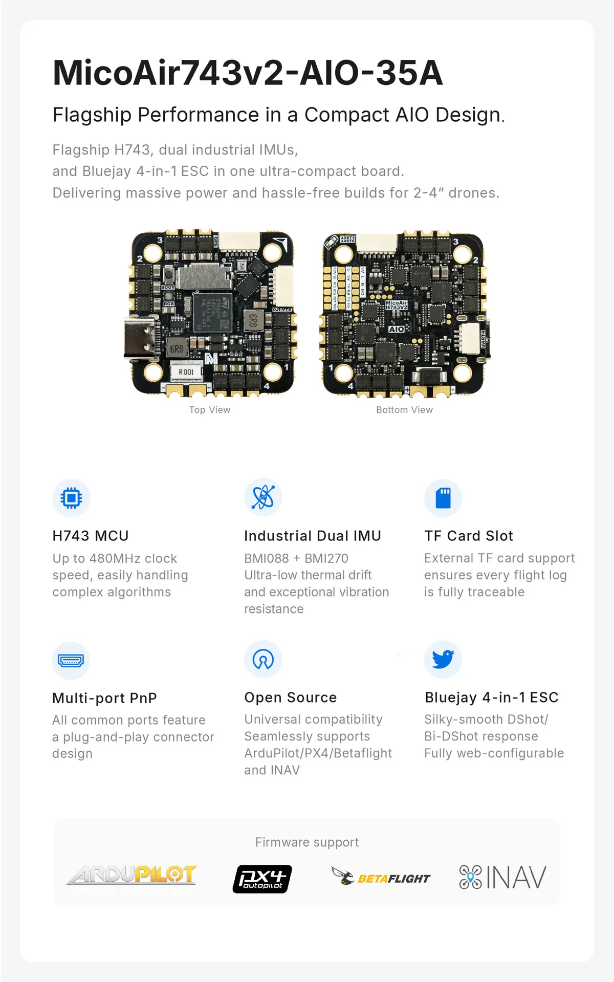
The MicoAir743v2-AIO-35A integrates an H743 flight controller and a four-in-one ESC on a single board with a 25.5 × 25.5 mm mounting pattern. The flight-controller section features a 480 MHz STM32H743VIH6, dual BMI088 + BMI270 IMUs, an SPL06 barometer, and microSD flight-log storage. The ESC section consists of four 35 A Bluejay ESCs.
Key Features
STM32H743VIH6, 480 MHz, 2 MB Flash- Dual
BMI088 + BMI270IMUs SPL06barometer and microSD card slot- 7 UARTs, 8 motor outputs, 1 I²C bus, and 1 SWD interface
- LED-strip output, buzzer, BOOT button, and USB Type-C
- Two BEC outputs: 5 V / 2 A and 12 V / 2 A
- Onboard battery-voltage and current sensing
- Direct interface for DJI O3/O4/O4 Pro, with MSP DisplayPort support
- 4 × 35 A Bluejay ESCs at 48 kHz, supporting DShot300 / DShot600 and bidirectional DShot
- Supports ArduPilot, PX4, INAV, Betaflight, and Skybrush firmware
Purchase
Hardware Specifications
Flight Controller
| Item | Specification |
|---|---|
| Main MCU | STM32H743VIH6, 480 MHz, 2 MB Flash |
| IMU | Dual BMI088 + BMI270 IMUs |
| Barometer | SPL06 |
| Magnetometer | No onboard magnetometer; supports an external I²C magnetometer |
| Analog OSD | None; HD video transmitters use MSP DisplayPort |
| Log storage | microSD card slot |
| UART | 7 ports: UART1, UART2, UART3, UART4, UART5, UART6, UART8 |
| Motor outputs | M1–M8; hardware supports DShot / bidirectional DShot, subject to firmware support |
| Additional output | LED strip; mapped to PWM11 in firmware resources |
| Peripheral interfaces | 1 I²C, 1 SWD, 2 ADC channels, and buzzer |
| USB | USB Type-C, with D+ / D− solder pads also provided |
ESC
| Item | Specification |
|---|---|
| ESC firmware | Bluejay 0.19.2 |
| PWM frequency | 48 kHz |
| Supported protocols | DShot300, DShot600, bidirectional DShot |
| Continuous current | 35 A × 4; adequate cooling is required |
| Battery input | 2–6S LiPo |
| Recommended starting protocol | DShot300 |
The 35 A continuous-current rating depends on propeller airflow, ambient temperature, and cooling conditions.
Power and Mechanical Specifications
| Item | Specification |
|---|---|
| Main power input | 2–6S LiPo |
| 5 V BEC | Up to 2 A for receivers, GPS modules, optical-flow sensors, and other peripherals |
| 12 V BEC | Up to 2 A for DJI O3/O4/O4 Pro and similar devices |
Voltage and Current Scaling Factors
| Parameter | ArduPilot | PX4 | Betaflight | INAV |
|---|---|---|---|---|
| Voltage Factor | 21.12 | 21.12 | 211 | 211 |
| Current Factor | 14.14 | 14.14 | 707 | 707 |
Dimensions and Installation
| Item | Specification |
|---|---|
| Mounting pattern | 25.5 × 25.5 mm |
| Mounting-hole diameter | Φ3 mm |
| Overall dimensions | 36 × 36 × 8 mm |
| Weight | 10 g |
The AIO must be installed at a 45° angle.
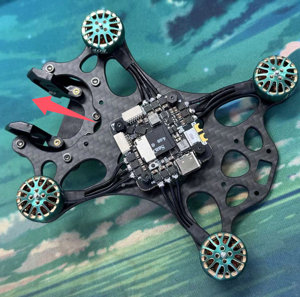
- By default, the arrow on the board should point toward the nose, with the component labels facing upward.
- Secure the board with insulated vibration-damping standoffs, ensuring that screws and carbon-fiber plates do not contact pads or components.
- Keep the ESC MOS area ventilated. Do not completely cover it with foam, double-sided tape, or wiring harnesses.
Interfaces and Power
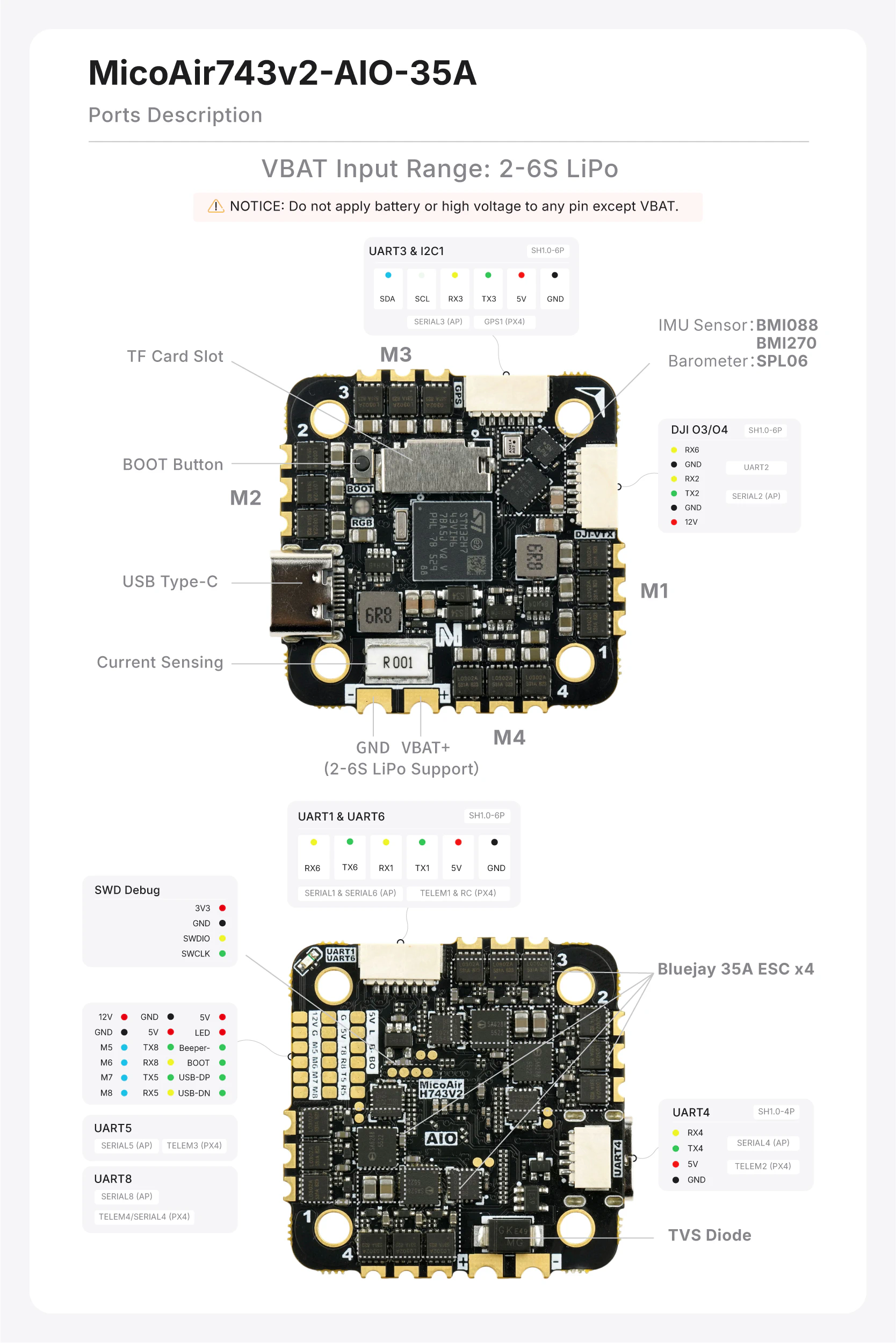
Interface Definitions
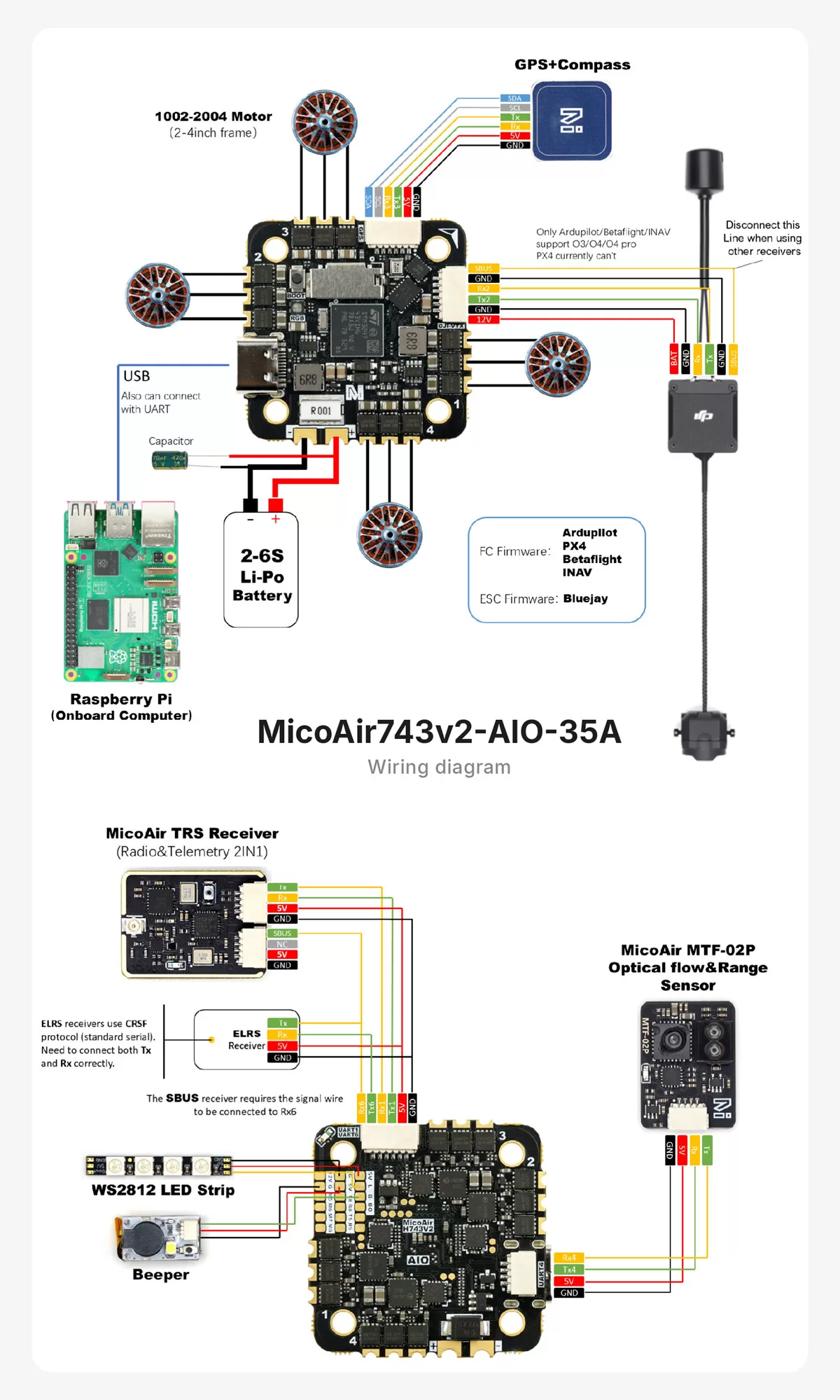
Typical Wiring
Power Rules
| Interface | Voltage | Typical Use | Notes |
|---|---|---|---|
VBAT | 2–6S | Main power for the flight controller and four-in-one ESC | Never reverse the polarity; verify the battery specification before soldering |
5V | 5 V | Receiver, GPS, optical-flow sensor, rangefinder, and similar peripherals | Total load must not exceed 2 A |
12V | 12 V | DJI O3/O4/O4 Pro, cameras, and similar devices | Do not connect devices rated for 5 V only |
GND | 0 V | Power and signal ground reference |
Pin 1 of the SH1.0-6P HD video-transmitter connector supplies 12 V. Before connecting a video transmitter, verify the connector orientation and wire order. Incorrect wiring may damage both the video transmitter and the flight controller.
UART wiring normally follows “flight-controller TX → peripheral RX” and “flight-controller RX → peripheral TX,” with GND also connected. For one-way protocols, connect only the signal lines required by the protocol.
Serial-Port Mapping
ArduPilot Serial-Port Mapping
| ArduPilot Port | Physical Interface | Default Use / Capability |
|---|---|---|
SERIAL0 | USB | USB virtual serial port |
SERIAL1 | UART1 | MAVLink2, with DMA support |
SERIAL2 | UART2 | DisplayPort, with DMA support |
SERIAL3 | UART3 | GPS, with DMA support |
SERIAL4 | UART4 | MAVLink2, with DMA support |
SERIAL5 | UART5 | General-purpose serial port, with DMA support |
SERIAL6 | UART6 | RC input, with DMA support |
SERIAL8 | UART8 | General-purpose serial port, with DMA support |
PX4 Serial-Port Mapping
| PX4 Device | PX4 Interface Name | Physical Interface |
|---|---|---|
ttyACM0 | USB | USB virtual serial port |
ttyS0 | TELEM1 | UART1 |
ttyS1 | GPS2 | UART2 |
ttyS2 | GPS1 | UART3 |
ttyS3 | TELEM2 | UART4 |
ttyS4 | TELEM3 | UART5 |
ttyS5 | RC | UART6 |
ttyS7 | TELEM4 / SERIAL4 | UART8 |
PWM Outputs
The flight controller provides eight motor outputs, M1–M8. The hardware supports DShot and bidirectional DShot, with final capabilities determined by the flight-controller firmware. The LED pad is mapped to PWM11 in firmware resources, so the firmware may report “up to 9 PWM resources”; only M1–M8 are motor pads.
PWM Timer Groups
| Group | Channels | Description |
|---|---|---|
| Group 1 | PWM1, PWM2, PWM3, PWM4 | Channels in the same group generally require compatible protocols and frequencies |
| Group 2 | PWM5, PWM6 | Shared group constraints |
| Group 3 | PWM7, PWM8, PWM11 | PWM11 is the LED pad |
When PWM11 is configured for a serial LED, PWM7 and PWM8 remain subject to the same timer-group constraints and may no longer support output settings that are incompatible with the serial LED.
ESC Configuration
Bluejay 0.19.2- Start with
DShot300. - Bidirectional DShot must be supported by both the flight-controller firmware and the ESC firmware.
- PX4 and INAV do not currently support bidirectional DShot. Refer to the relevant firmware release notes for future changes.
- Web-based ESC tool: ESC Configurator
Receiver
UART6 is the default RC input interface. On the H743, the RC function can also be reassigned to another UART.
| Protocol | Recommended Wiring | Notes |
|---|---|---|
| SBUS | Signal → RX6 | One-way signal; also connect power and GND |
| CRSF / ELRS | Receiver TX → RX6; receiver RX → TX6 | Supports telemetry |
| FPort | Signal → TX6 | Single-wire bidirectional protocol |
| DSM / SRXL | Signal → RX6 | Verify the receiver supply voltage |
| SRXL2 | Signal → TX6 | Configure serial-port options as required by the protocol in ArduPilot |
| PPM | Not supported | Use a serial receiver protocol |
To move RC input to another UART in ArduPilot, set the target
SERIALn_PROTOCOLto23and assign the originalSERIAL6_PROTOCOLto another function.
OSD and HD Video Transmitters
This AIO does not include an AT7456E analog OSD. OSD data is sent to DJI O3/O4/O4 Pro and other HD video transmitters through MSP DisplayPort.
- The SH1.0-6P connector uses UART2 by default
- ArduPilot can use
OSD_TYPE = 5(MSP DisplayPort) - The video-transmitter connector provides 12 V power
- PX4 support for DJI OSD varies by version; refer to the documentation for the PX4 version in use
Do not connect the 12 V pin on the video-transmitter interface to a 5 V camera, receiver, or general-purpose serial peripheral.
Battery Monitoring, Magnetometer, and I²C
Battery Monitoring
The flight controller includes voltage and current sensing. Default factors are listed in the comparison table under “Hardware Specifications.” Use a multimeter and a known current load as the reference when calibrating.
Magnetometer and I²C
- No onboard magnetometer
- An external magnetometer can be connected through
SDA/SCL - Keep the external magnetometer away from battery cables, motors, and the four-in-one ESC
- For I²C peripherals, verify supply voltage, address conflicts, and cable length
For autonomous flight and applications requiring accurate heading, use a GPS/magnetometer module positioned away from the power system. Recalibrate the magnetometer after completing the aircraft assembly.
Firmware
The MicoAir743v2-AIO-35A uses the same flight-controller firmware target as the MicoAir743v2 and supports ArduPilot, PX4, INAV, Betaflight, and Skybrush.
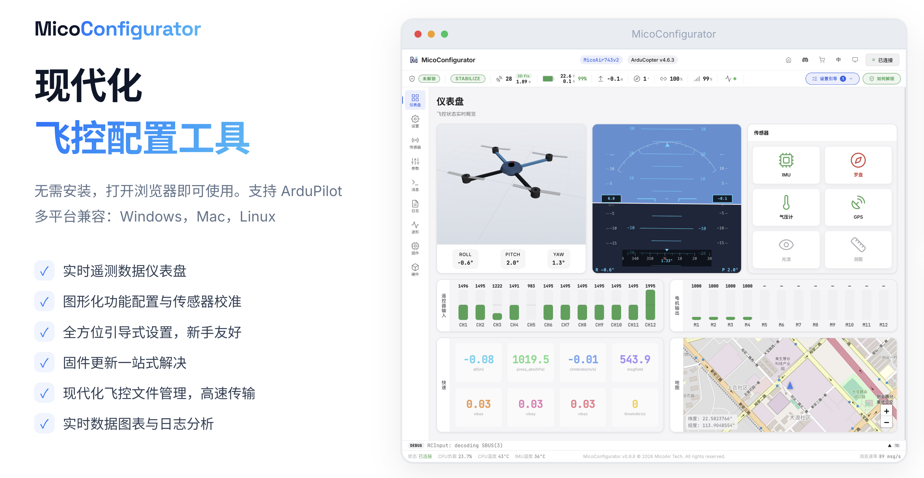
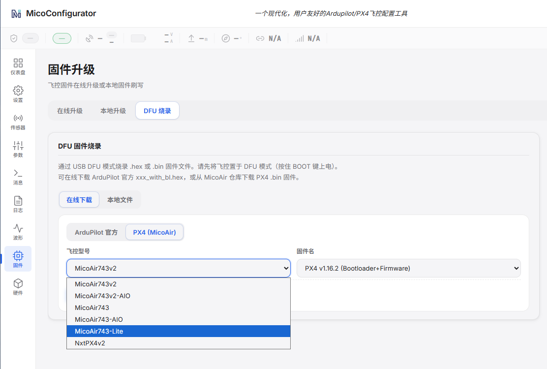
MicoConfigurator is a browser-based flight-controller configuration tool for Windows, macOS, and Linux. It can configure and debug the flight controller and update firmware online, from a local file, or in DFU mode.
Open MicoConfigurator in Chrome or Edge. After entering DFU mode, you can select the board and firmware directly in the browser to flash it. Windows requires a DFU driver.
ArduPilot
- Firmware target:
MicoAir743v2 - Included in the official hardware support list starting with ArduPilot 4.6.0
- Firmware can be flashed online through MicoConfigurator or Mission Planner
- Official ArduPilot hardware definition
- Official ArduPilot firmware downloads
- ArduPilot Custom Firmware Builder
The MicoAir743v2-AIO and MicoAir743v2 share the same firmware. When downloading or flashing firmware, select the
MicoAir743v2target. Do not select similarly named AIO firmware targets.
PX4
- Firmware target:
micoair_h743-v2 - Included in the official hardware support list starting with PX4 1.16.0
- Official PX4 hardware definition
- PX4 releases
- PX4 firmware provided by MicoAir
Official PX4 firmware build guide
Build the bootloader:
make micoair_h743-v2_bootloader
Build the default firmware:
make micoair_h743-v2_default
INAV
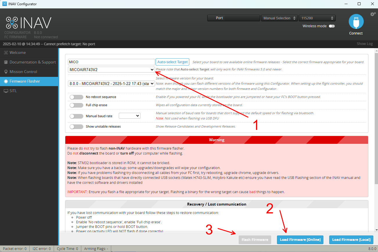
- Firmware target:
MICOAIR743V2_EXTMAG - This target is available starting with INAV 8.0.1 RC1
- MicoAir743v2 INAV firmware
Betaflight
- Use the corresponding MicoAir743v2 firmware provided in the MicoAir repository
- MicoAir743v2 Betaflight firmware
Skybrush
- Drone-show firmware based on ArduPilot
- Download Skybrush firmware
Troubleshooting
USB Is Not Detected
- Replace the cable with a USB Type-C cable known to support data transfer.
- Avoid underpowered hubs; connect directly to a main USB port on the computer.
- Check whether the operating system detects a serial or DFU device.
- If the board still cannot connect, follow the preceding procedure to enter DFU mode and verify the hardware connection.
No Receiver Data
- Check that TX and RX are cross-connected correctly.
- Connect an SBUS signal to
RX6; CRSF/ELRS normally requires bothTX6andRX6. - Verify the serial protocol, baud rate, and whether UART6 is assigned to another function.
- Confirm that the receiver supply voltage is correct and that the receiver and flight controller share a common ground.
Motors Do Not Spin or Rotate in the Wrong Direction During Testing
- Remove the propellers and connect the main battery before testing the motors.
- Verify motor numbering, output protocol, and ESC power.
- Confirm that the flight-controller ESC protocol is set to
DShot300; Bluejay ESC firmware does not support PWM input.
Related Resources
- MicoConfigurator
- Flight-Controller Firmware Flashing Tutorial
- ArduPilot Basic Configuration Tutorial
- Connect a Computer to MicoAir H743v2/Lite via Bluetooth
- Official ArduPilot documentation
- Official PX4 documentation
- Download QGroundControl
- INAV Configurator
- Betaflight Configurator
Appendix A: Pinout Table
| Function Category | Device / Purpose | Bus / Peripheral | Signal | MCU Pin |
|---|---|---|---|---|
| IMU | BMI270 | SPI3 | MOSI | PD6 |
| IMU | BMI270 | SPI3 | MISO | PB4 |
| IMU | BMI270 | SPI3 | SCLK | PB3 |
| IMU | BMI270 | GPIO | CS | PA15 |
| IMU | BMI270 | GPIO | DRDY | PB7 |
| IMU | BMI088 | SPI2 | MOSI | PC3 |
| IMU | BMI088 | SPI2 | MISO | PC2 |
| IMU | BMI088 | SPI2 | SCLK | PD3 |
| IMU | BMI088 | GPIO | GYRO_CS | PD5 |
| IMU | BMI088 | GPIO | ACCEL_CS | PD4 |
| IMU | BMI088 | GPIO | GYRO_DRDY | PC15 |
| IMU | BMI088 | GPIO | ACCEL_DRDY | PC14 |
| Barometer | SPL06 | I²C2 | SCL | PB10 |
| Barometer | SPL06 | I²C2 | SDA | PB11 |
| Barometer | SPL06 | GPIO | DRDY | PD0 |
| Motor output | PWM | TIM1 / CH4 | M1 | PE14 |
| Motor output | PWM | TIM1 / CH3 | M2 | PE13 |
| Motor output | PWM | TIM1 / CH2 | M3 | PE11 |
| Motor output | PWM | TIM1 / CH1 | M4 | PE9 |
| Motor output | PWM | TIM3 / CH4 | M5 | PB1 |
| Motor output | PWM | TIM3 / CH3 | M6 | PB0 |
| Motor output | PWM | TIM4 / CH1 | M7 | PD12 |
| Motor output | PWM | TIM4 / CH2 | M8 | PD13 |
| LED strip | PWM | TIM4 / CH3 | LED | PD14 |
| Buzzer | GPIO | — | Buzzer | PD15 |
| External oscillator | External | 8 MHz | OSC_IN | PH0 |
| External oscillator | External | 8 MHz | OSC_OUT | PH1 |
| Status LED | GPIO_OUTPUT | RED | — | PE3 |
| Status LED | GPIO_OUTPUT | BLUE | — | PE4 |
| Status LED | GPIO_OUTPUT | GREEN | — | PE2 |
| Button | — | BOOT | — | BOOT0 |
| I²C | Peripheral interface | I²C1 | SDA | PB9 |
| I²C | Peripheral interface | I²C1 | SCL | PB8 |
| UART | UART1 | UART1 | TX | PA9 |
| UART | UART1 | UART1 | RX | PA10 |
| UART | VTX-HD | UART2 | TX | PA2 |
| UART | VTX-HD | UART2 | RX | PA3 |
| UART | GPS | UART3 | TX | PD8 |
| UART | GPS | UART3 | RX | PD9 |
| UART | UART4 | UART4 | TX | PA0 |
| UART | UART4 | UART4 | RX | PA1 |
| UART | UART5 | UART5 | TX | PB6 |
| UART | UART5 | UART5 | RX | PB5 |
| UART | RCIN | UART6 | TX | PC6 |
| UART | RCIN | UART6 | RX | PC7 |
| UART | UART8 | UART8 | TX | PE1 |
| UART | UART8 | UART8 | RX | PE0 |
| USB | USB | USB | USB_DM | PA11 |
| USB | USB | USB | USB_DP | PA12 |
| SD card | microSD | SDMMC1 | D0 | PC8 |
| SD card | microSD | SDMMC1 | D1 | PC9 |
| SD card | microSD | SDMMC1 | D2 | PC10 |
| SD card | microSD | SDMMC1 | D3 | PC11 |
| SD card | microSD | SDMMC1 | CLK | PC12 |
| SD card | microSD | SDMMC1 | CMD | PD2 |
| Debug interface | SWD | SWD | SWDIO | PA13 |
| Debug interface | SWD | SWD | SWCLK | PA14 |
| Battery-voltage sensing | Approx. 1:21 divider ratio | ADC | Voltage | PC0 |
| Current sensing | Onboard current sensing | ADC | Current | PC1 |