

Docs directory
Table of contents
MicoAir-WiFi-Link Multi-Drone Networking Guide
This guide explains how to configure one or more MicoAir-WiFi-Link modules in STA mode so a ground control station can receive MAVLink telemetry from multiple flight controllers over the same LAN.
STA Mode and Configuration Preparation
STA Mode Overview
In STA mode, the MicoAir-WiFi-Link operates as a wireless client and connects to an existing router. The flight controller connects to the module through a serial port, while the GCS computer connects to the same router over Wi-Fi or Ethernet. Once configured, one GCS can monitor and control multiple drones over the LAN.
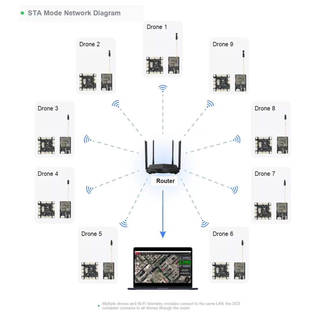
Before configuring STA mode, determine these parameters:
| Parameter | AT Command | Description |
|---|---|---|
| Router Wi-Fi SSID | AT+SSID | SSID of the wireless network the module will join |
| Router Wi-Fi password | AT+PWD | Password for the wireless network |
| Module IP address | AT+MIP | Static module address on the LAN |
| Target IP address | AT+TIP | IPv4 address of the GCS computer |
| Gateway address | AT+GW | Router default gateway |
| UDP port | AT+PORT | GCS listening port, typically 14550 |
AT+TIPis the parameter most commonly configured incorrectly in STA mode. It must be the IPv4 address assigned to the GCS computer on the target router.
Computer IPv4 Address
- Connect the GCS computer to the router.
- Open Command Prompt in Windows.
- Run
ipconfig. - Locate the IPv4 Address of the active adapter.
ipconfig

IPv4 Address. . . . . . . . . . . : 192.168.8.211
Default Gateway . . . . . . . . . : 192.168.8.1
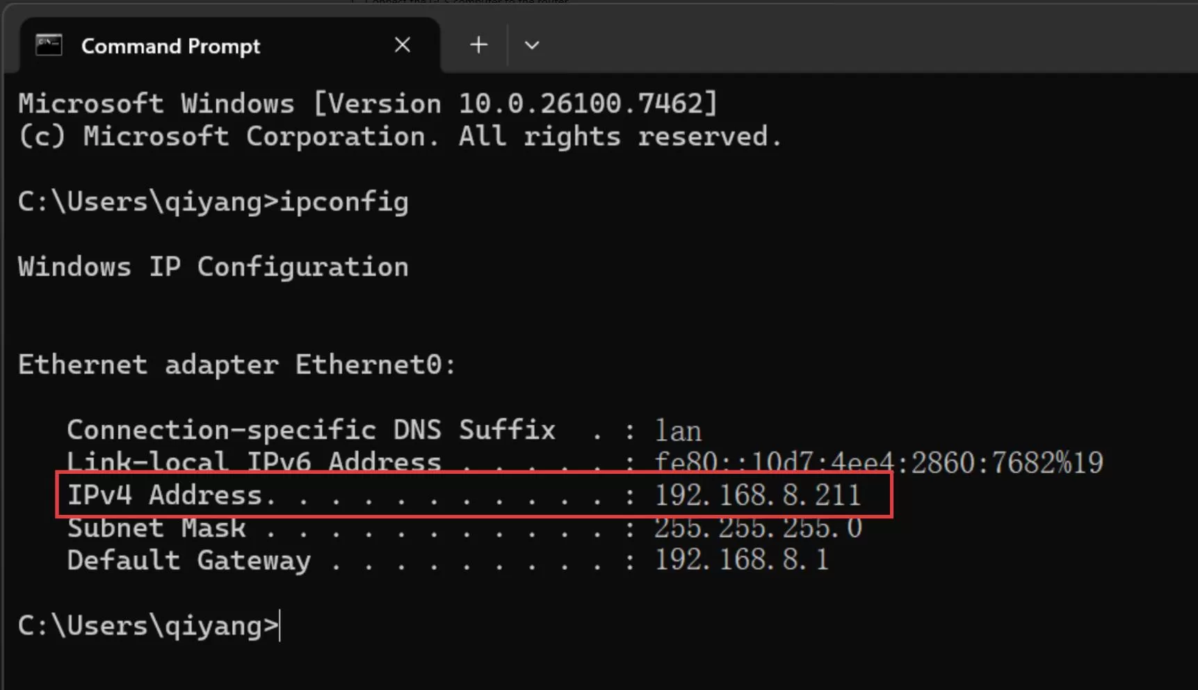
Based on the example, plan the network as follows:
| Parameter | Example Value |
|---|---|
| GCS computer IP | 192.168.8.211 |
| Wi-Fi telemetry module IP | 192.168.8.213 |
| Gateway IP | 192.168.8.1 |
| UDP port | 14550 |
AT+MIP must be in the same subnet as the GCS and gateway and must not duplicate another LAN address. If the computer changes networks or receives a new address, update AT+TIP.
Hardware Connections
Connection for Module Configuration
Connect the module directly to the computer with a USB Type-C cable that supports data. Verify its COM port in Windows Device Manager. If no port appears, install the CH340 driver or try another data-capable cable.
Connection for Flight Operations
Use the supplied cable to connect the module to the flight controller. This guide assumes TELEM1: connect the GH1.25-4Pin end to the module and the SH1.0-4Pin end to TELEM1.
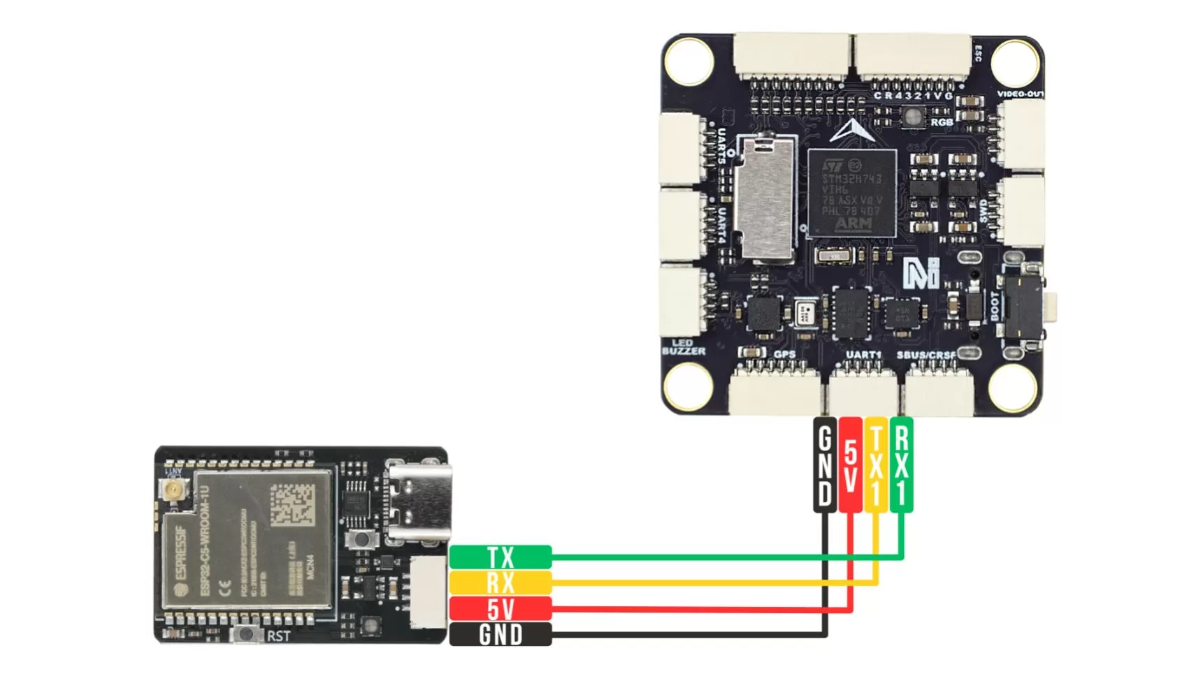
Always verify the serial port mapping for the specific flight controller before changing firmware parameters.
Wi-Fi Module Configuration
Testing AT Command
- Open a serial terminal such as SSCOM.
- Select the module COM port and set 115200 baud.
- Enable AddCRLF or terminate every command with CRLF.
- Send
ATand expectOK.
AT
OK
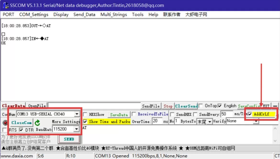
If the module does not respond, check that:
- The correct COM port is selected.
- The baud rate is 115200.
- CRLF termination is enabled.
- The Type-C cable supports data.
Reading the Configuration
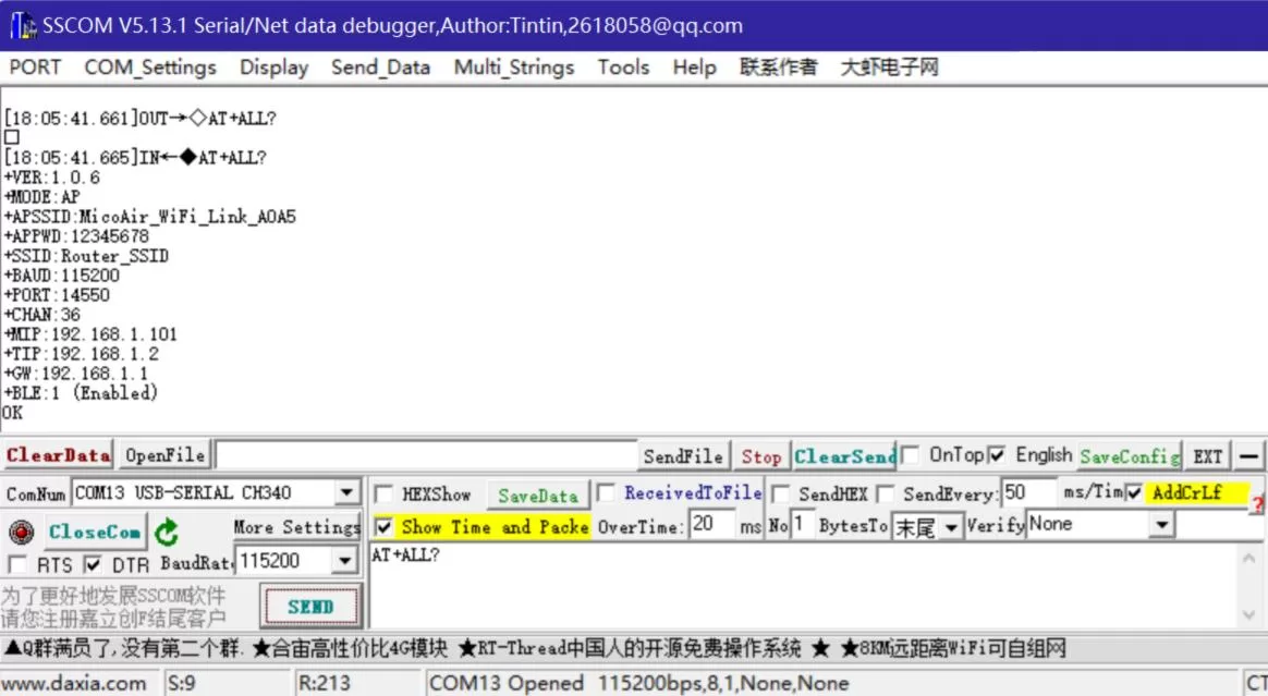
Send AT+ALL? to display the mode, SSID, serial baud rate, UDP port, local IP, target IP, gateway, and other parameters.
AT+ALL?
STA Network Parameters
Use serial AT commands throughout initial setup to avoid mixing configuration methods. Replace the following examples with your actual network parameters.
AT+SSID=MicoAir_5G
AT+PWD=12345678
AT+MIP=192.168.8.213
AT+TIP=192.168.8.211
AT+GW=192.168.8.1
AT+PORT=14550
AT+BAUD=115200
AT+MODE=1
AT+RST
Configuration Verification
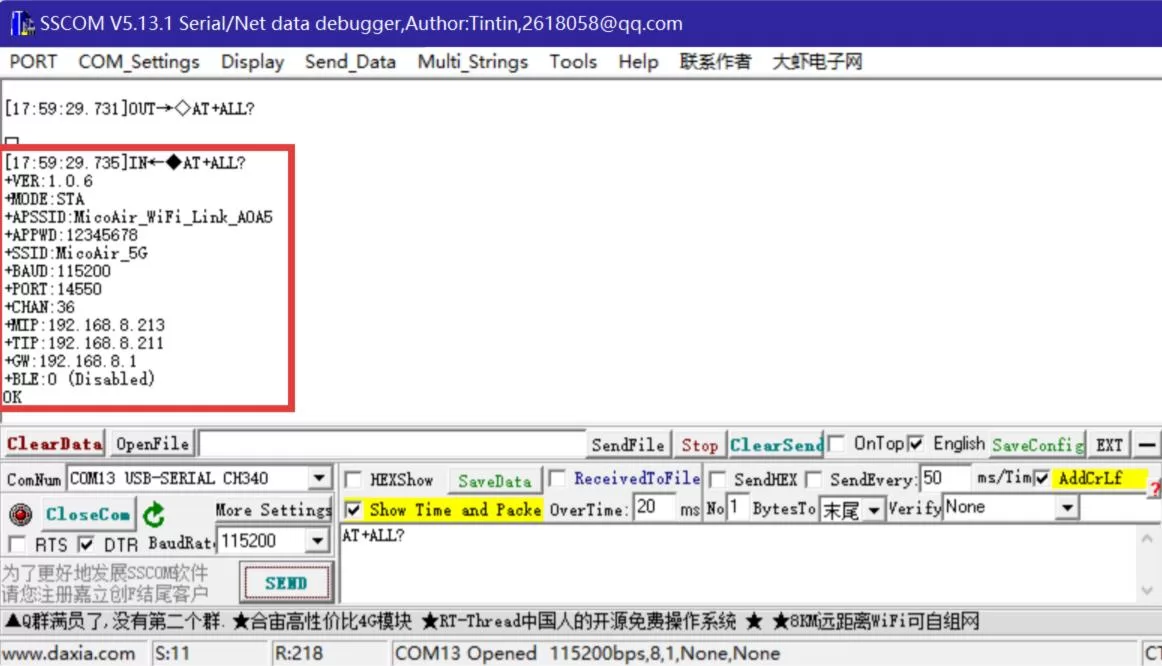
The module restarts after its mode changes. Reopen the serial port, send AT+ALL?, and verify MODE, SSID, BAUD, PORT, MIP, TIP, and GW.
AT+ALL?
Flight Controller Configuration
Configure the connected flight controller serial port for MAVLink and match its baud rate to AT+BAUD.
ArduPilot Configuration
- Connect the flight controller over USB or another supported connection.
- Open MicoConfigurator and connect to the flight controller.
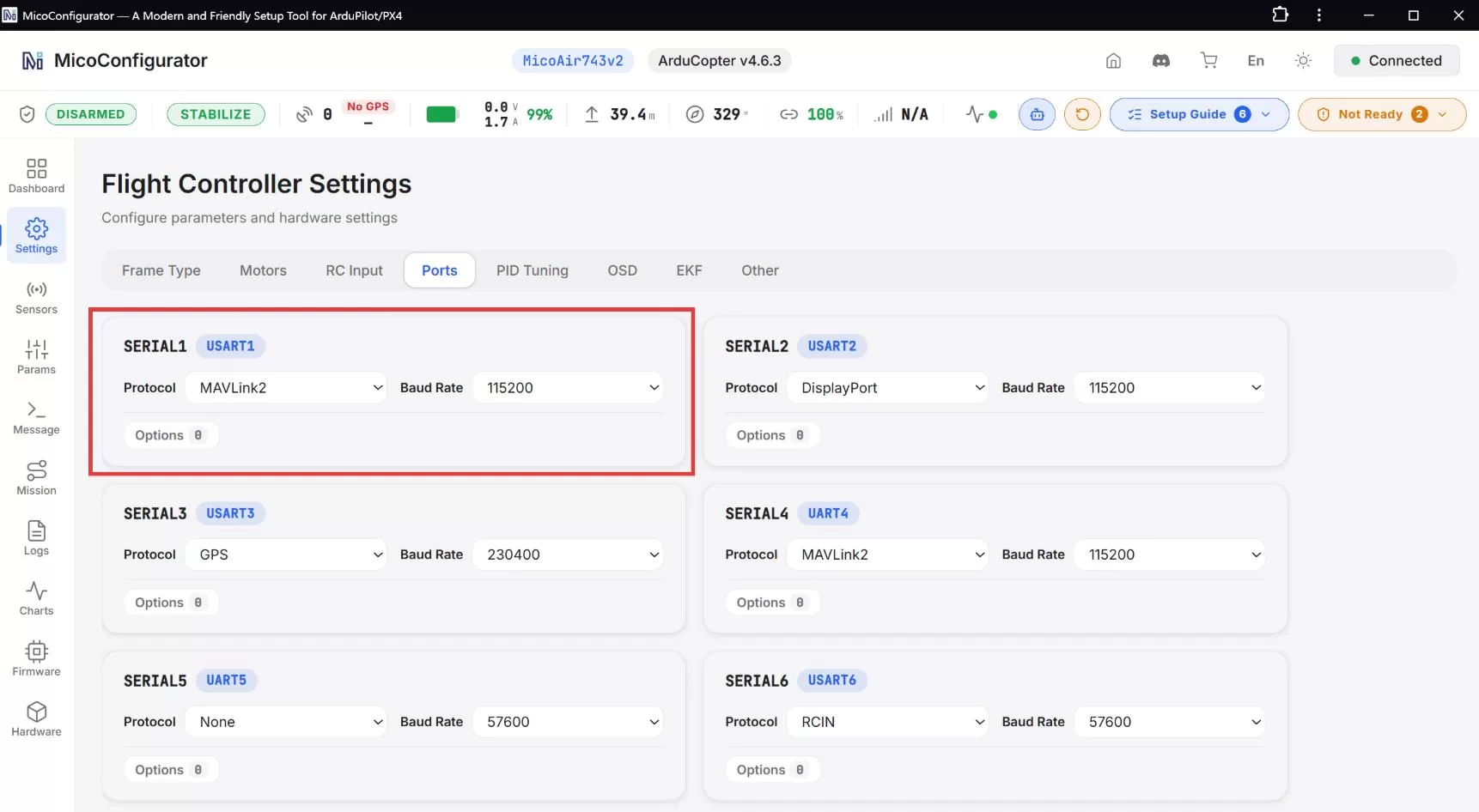
- Go to Settings > Ports.
- Locate the serial port connected to the module.
SERIAL1_PROTOCOL = MAVLink2
SERIAL1_BAUD = 115200
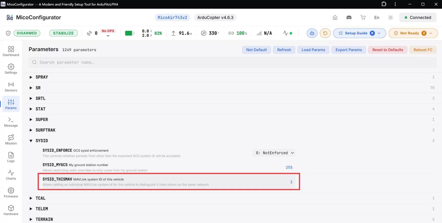
Each drone in a multi-drone system needs a unique SYSID_THISMAV. A single drone can normally keep 1. Restart the flight controller if required.
SYSID_THISMAV = 1
PX4 Configuration
- Connect the flight controller over USB or another supported connection.
- Open MicoConfigurator and connect to the flight controller.
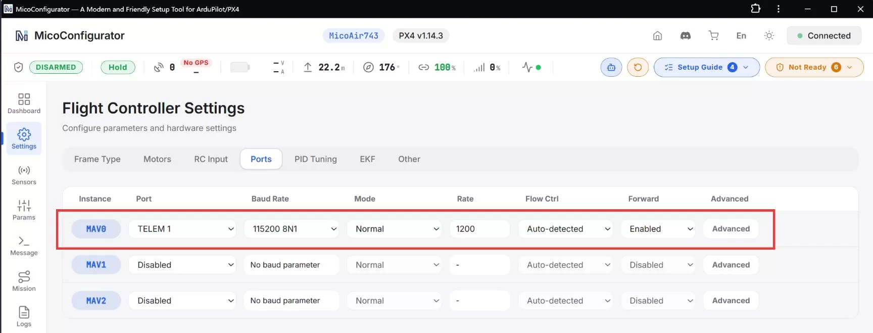
- Go to Settings > Ports.
- If the module uses TELEM1, apply the parameters below.
MAV_0_CONFIG = TELEM1
MAV_0_MODE = Normal
SER_TEL1_BAUD = 115200 8N1
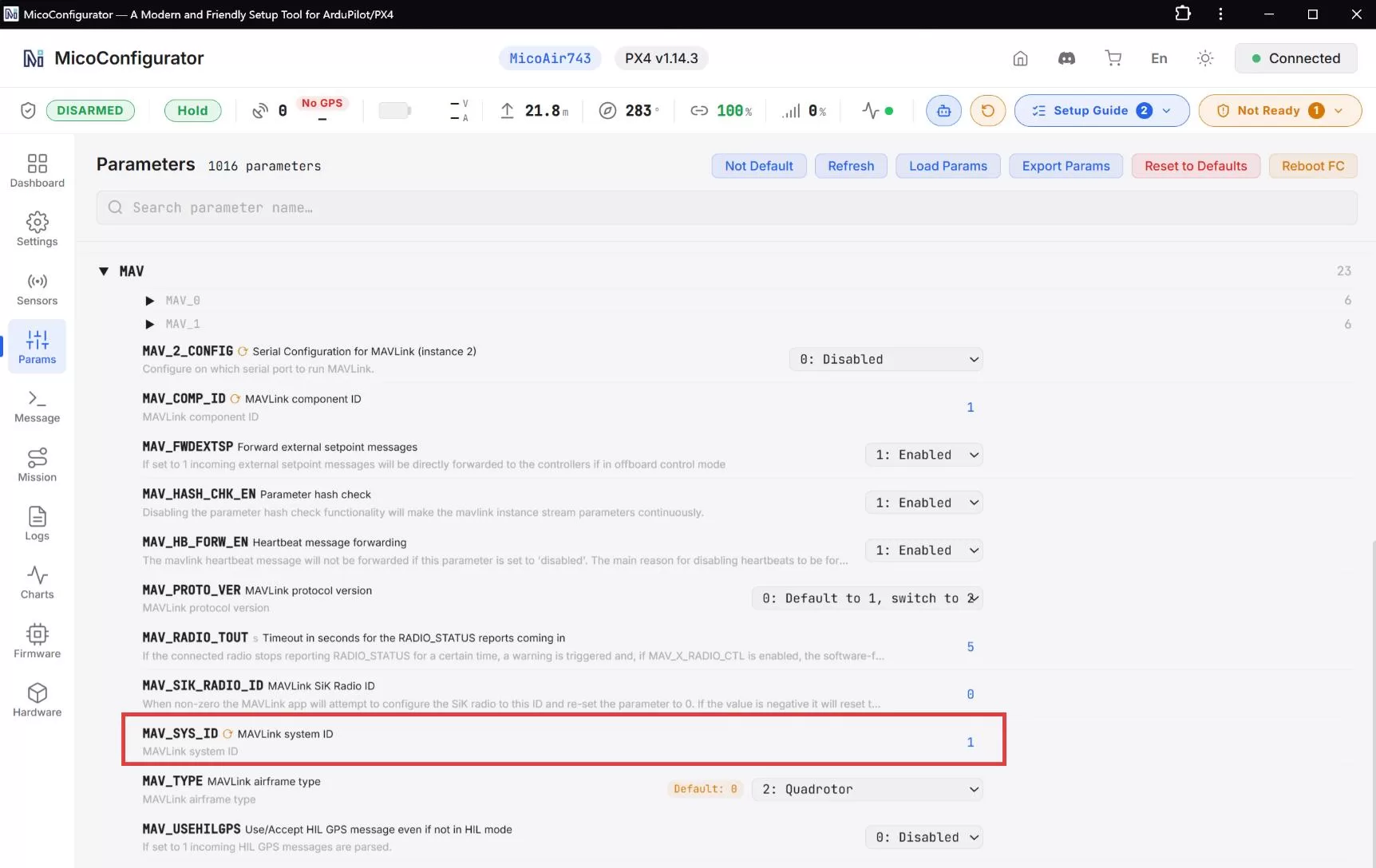
Each drone also needs a unique MAV_SYS_ID. A single drone can normally keep 1. Restart the flight controller after changing it.
MAV_SYS_ID = 1
GCS Connection
After configuring the module and flight controller, establish one UDP connection in the GCS. The same connection receives every drone and separates them by unique system ID.
Mission Planner
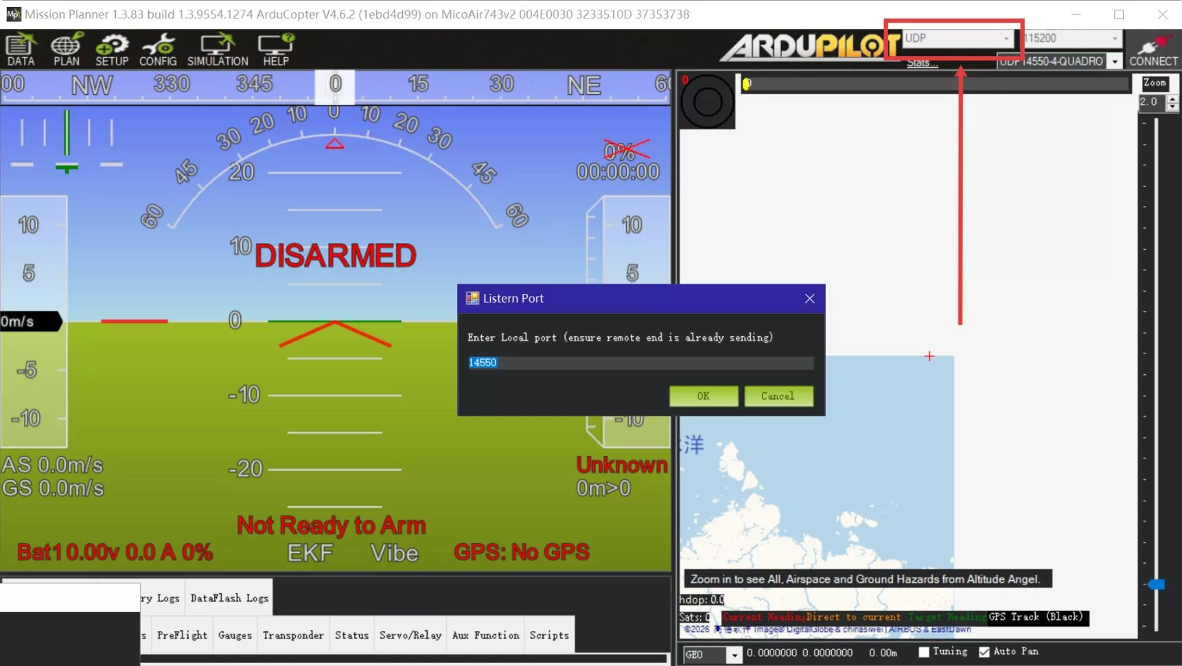
- Open Mission Planner.
- Select UDP.
- Set port 14550.
- Click Connect and wait for detection.
QGroundControl
- Open QGroundControl.
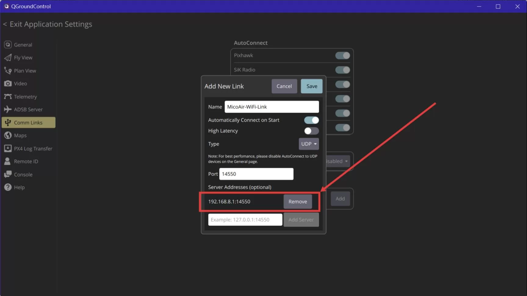
- Go to Application Settings > Comm Links.
- Enable automatic UDP or add a UDP link.
- Set listening port 14550.
- Connect and wait for detection.
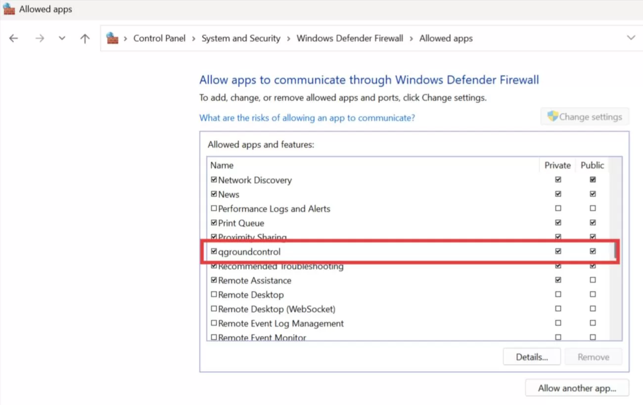
If no telemetry arrives, first check whether Windows Firewall blocks UDP traffic for Mission Planner or QGroundControl.
Configuration Example for Multiple Drones
STA mode allows multiple drones to share one router. Every Wi-Fi module needs a unique local IP, and every flight controller needs a unique system ID.
Network Plan for Three Drones
| Device | IP Address / ID |
|---|---|
| Router gateway | 192.168.8.1 |
| GCS computer | 192.168.8.211 |
| Drone 1 module | 192.168.8.212 |
| Drone 2 module | 192.168.8.213 |
| Drone 3 module | 192.168.8.214 |
| UDP port | 14550 |
Set AT+TIP on every module to 192.168.8.211 and give each module a different AT+MIP. A separate GCS connection is not required for each drone.
AT+TIP=192.168.8.211
Configuration Examples for Three Drones
Drone 1
AT+SSID=MicoAir_5G
AT+PWD=12345678
AT+MIP=192.168.8.212
AT+TIP=192.168.8.211
AT+GW=192.168.8.1
AT+PORT=14550
AT+BAUD=115200
AT+MODE=1

SYSID_THISMAV = 1
MAV_SYS_ID = 1
Drone 2
AT+SSID=MicoAir_5G
AT+PWD=12345678
AT+MIP=192.168.8.213
AT+TIP=192.168.8.211
AT+GW=192.168.8.1
AT+PORT=14550
AT+BAUD=115200
AT+MODE=1

SYSID_THISMAV = 2
MAV_SYS_ID = 2
Drone 3
AT+SSID=MicoAir_5G
AT+PWD=12345678
AT+MIP=192.168.8.214
AT+TIP=192.168.8.211
AT+GW=192.168.8.1
AT+PORT=14550
AT+BAUD=115200
AT+MODE=1

SYSID_THISMAV = 3
MAV_SYS_ID = 3
Four-Drone GCS Examples
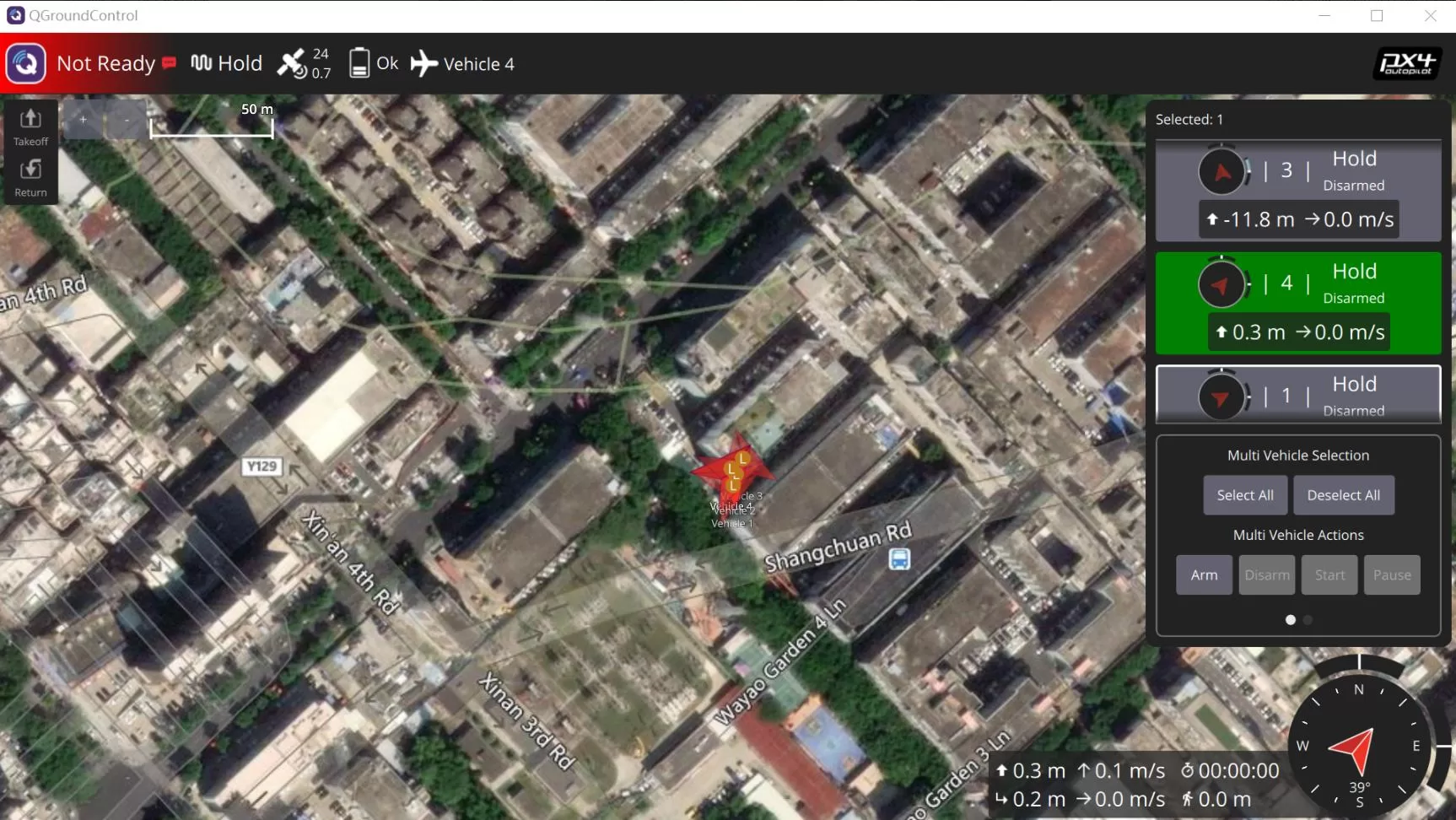
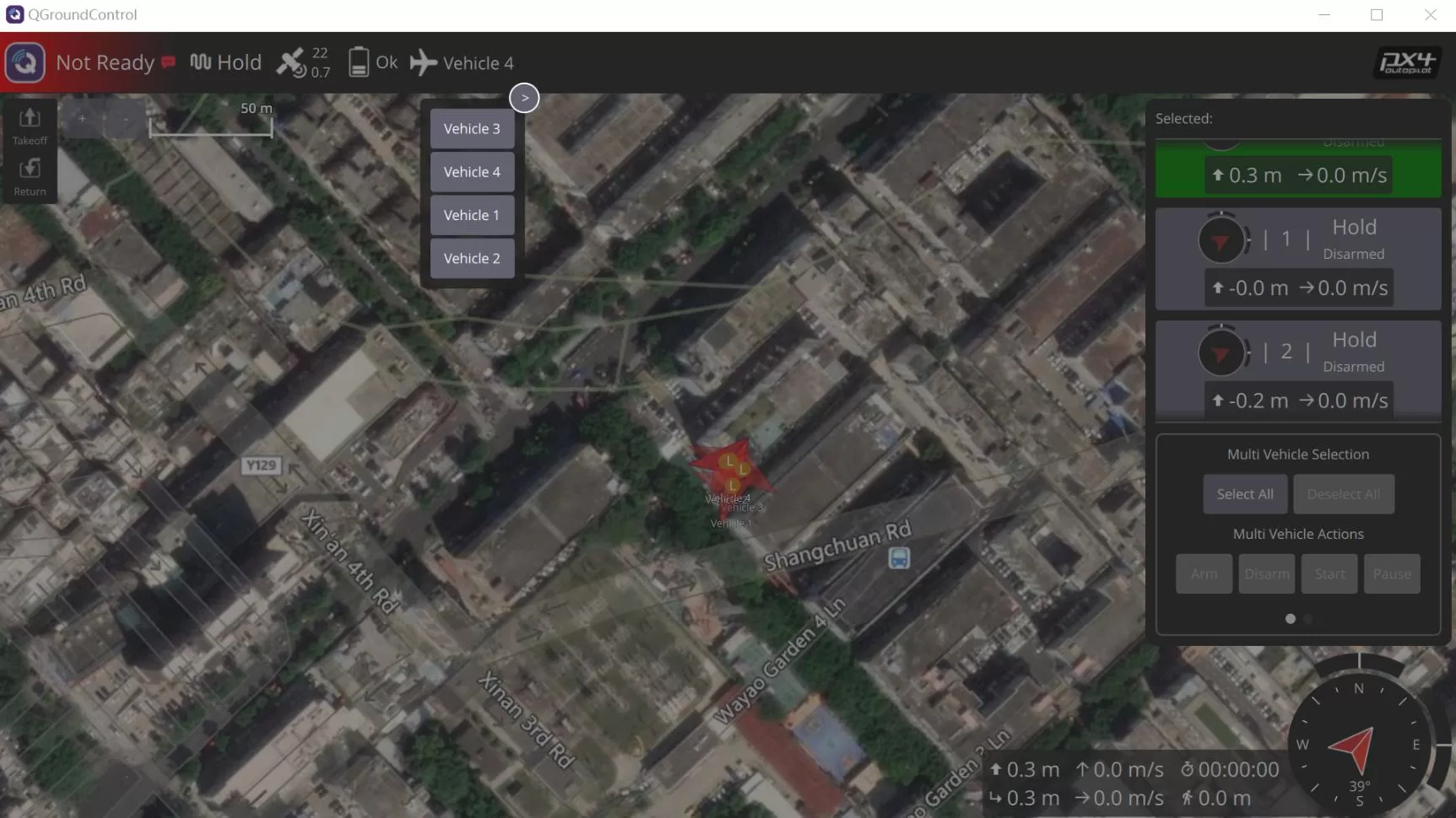
Four drones using PX4 and MicoAir-WiFi-Link:
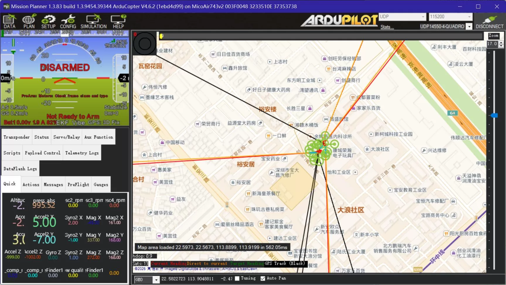
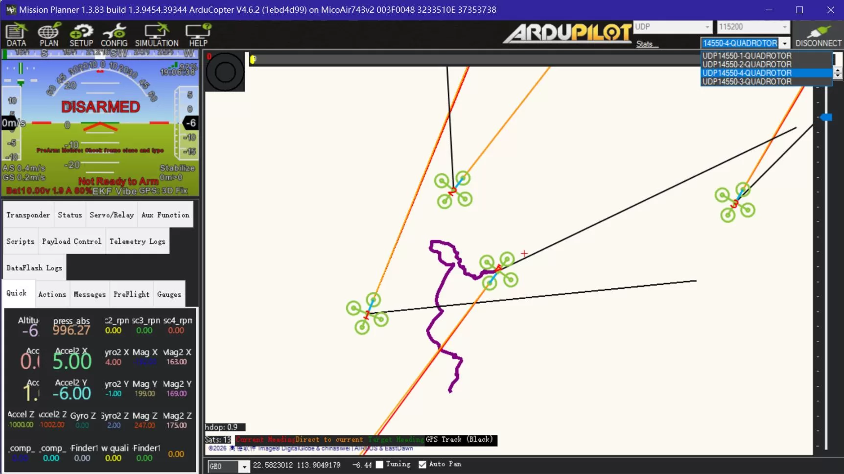
Four drones using ArduPilot and MicoAir-WiFi-Link:
Operational Notes for Multiple Drones
- Use a unique
AT+MIPon every module. - Point every
AT+TIPto the GCS computer. - Use a unique flight controller system ID.
- Update every
AT+TIPif the GCS address changes. - Reserve a static address for the GCS on the router.
- Check for duplicate system IDs when some drones are missing.
Troubleshooting
No Response to AT Commands
- Confirm the Type-C cable supports data.
- Confirm the correct serial port.
- Confirm 115200 baud.
- Confirm AddCRLF is enabled.
Module Cannot Connect to the Router
- Verify
AT+SSID. - Verify
AT+PWD. - Verify the router permits the module.
- Verify STA mode.
No Telemetry Data at the GCS
- The computer IP matches
AT+TIP. AT+MIP,AT+TIP, andAT+GWshare a subnet.- The GCS listens on UDP 14550.
- Windows Firewall allows the GCS.
- The flight controller port uses MAVLink.
- The serial baud rate matches
AT+BAUD. - TX and RX are crossed correctly.
Parameter Changes Do Not Take Effect
Send AT+RST, then query AT+ALL? again and confirm the new values were saved.
AT+RST
AT+ALL?
Restoring Factory Defaults
Send AT+RESET, then configure STA mode again from the beginning.
AT+RESET