

Docs directory
Table of contents
MicoAssistant User Guide
About MicoAssistant
MicoAssistant is a web application for connecting, testing, and configuring MicoAir telemetry radios, optical-flow sensors, and rangefinders. No desktop client is required. In Chrome or Edge, users can read device information, change parameters, and view sensor data.
Open MicoAssistant at https://micoair.com/assistant/
Connecting a Device to MicoAssistant
Connect the Device to the Computer and Install Its Driver
Before using MicoAssistant, connect the product correctly to the computer and confirm that Windows recognizes the corresponding serial port.
If the product has a USB Type-C port, connect it directly with a USB data cable. If the product provides only a UART interface, use a USB-to-TTL adapter.
Products with a USB Type-C Port
If the product has a USB Type-C port for configuration, a direct computer connection is recommended. This approach requires no additional wiring and avoids accidentally reversing TX and RX.
Products with Only a Serial Interface
If the product provides only a UART interface, connect it to the computer through a USB-to-TTL adapter. Common adapter chipsets include CP2102, CH340/CH341, and FT232.
The general wiring is as follows:
| Product Side | USB-to-TTL Side | Description |
|---|---|---|
| TX | RX | Transmit and receive signals must be crossed |
| RX | TX | Transmit and receive signals must be crossed |
| GND | GND | Both devices must share ground |
| VCC | Corresponding supply | Confirm the product's supply requirements |
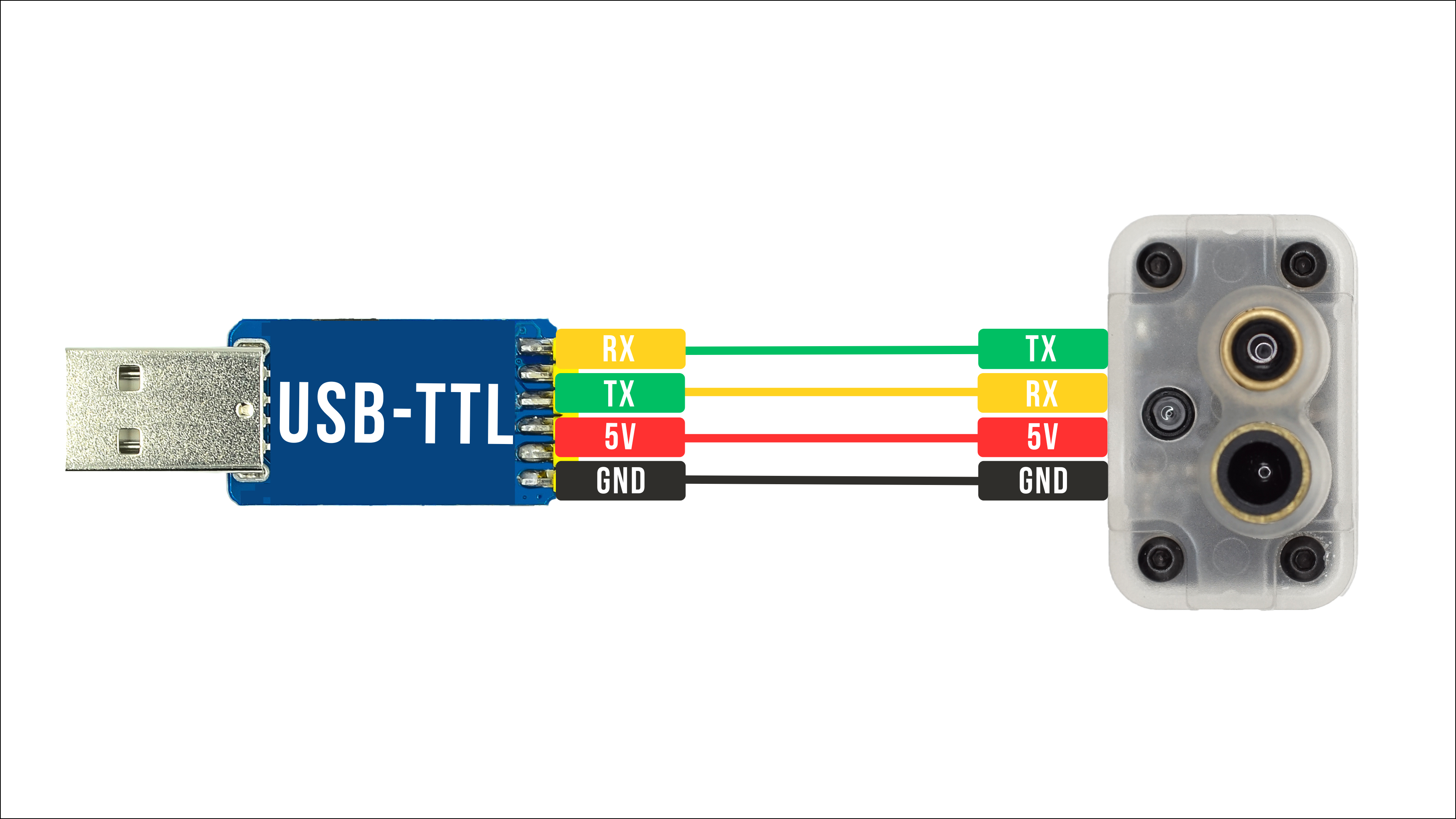
Do not determine pin functions from wire colors alone. Colors may vary between cable types and production batches. Follow the product connector labels and pinout, and confirm the required supply voltage and serial logic level before connecting the device.
Install the CP210x Driver
LR900-F/P, LR868-F, LR24-F/P, and devices that use a CP2102 adapter generally require the CP210x virtual COM-port driver.
Install the CH340/CH341 Driver
LR900-A, MicoAir-WiFi-Link, and devices using a CH340/CH341 adapter require the CH340/CH341 serial driver.
When using a USB-to-TTL adapter, install the driver for the chipset used by the adapter, not one selected according to the product being configured.
Check the Driver Status
After completing the wiring and driver installation, check the device under “Ports (COM & LPT)” in Windows Device Manager:
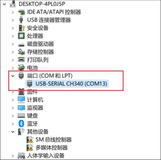
- A COM port appears normally: Windows recognizes the device, and you can proceed to MicoAssistant.
- The device icon has a yellow exclamation mark: the driver is not installed correctly; reinstall the appropriate driver.
- No new device appears: check the data cable, USB port, device power, and physical wiring.
- The device appears as an unknown device: identify the USB-to-serial chipset and install its driver.
Connect the Device in MicoAssistant
- Open MicoAssistant: https://micoair.com/assistant/.
- Confirm that the device is connected to the computer and appears as a normal COM port in Device Manager.
- Click “Select Port,” then choose the device's COM port in the browser dialog.
- Set the connection baud rate. Sensors such as the MTF-01/01P/02/02P normally use
115200; standard MicoAir telemetry radios use57600by default.
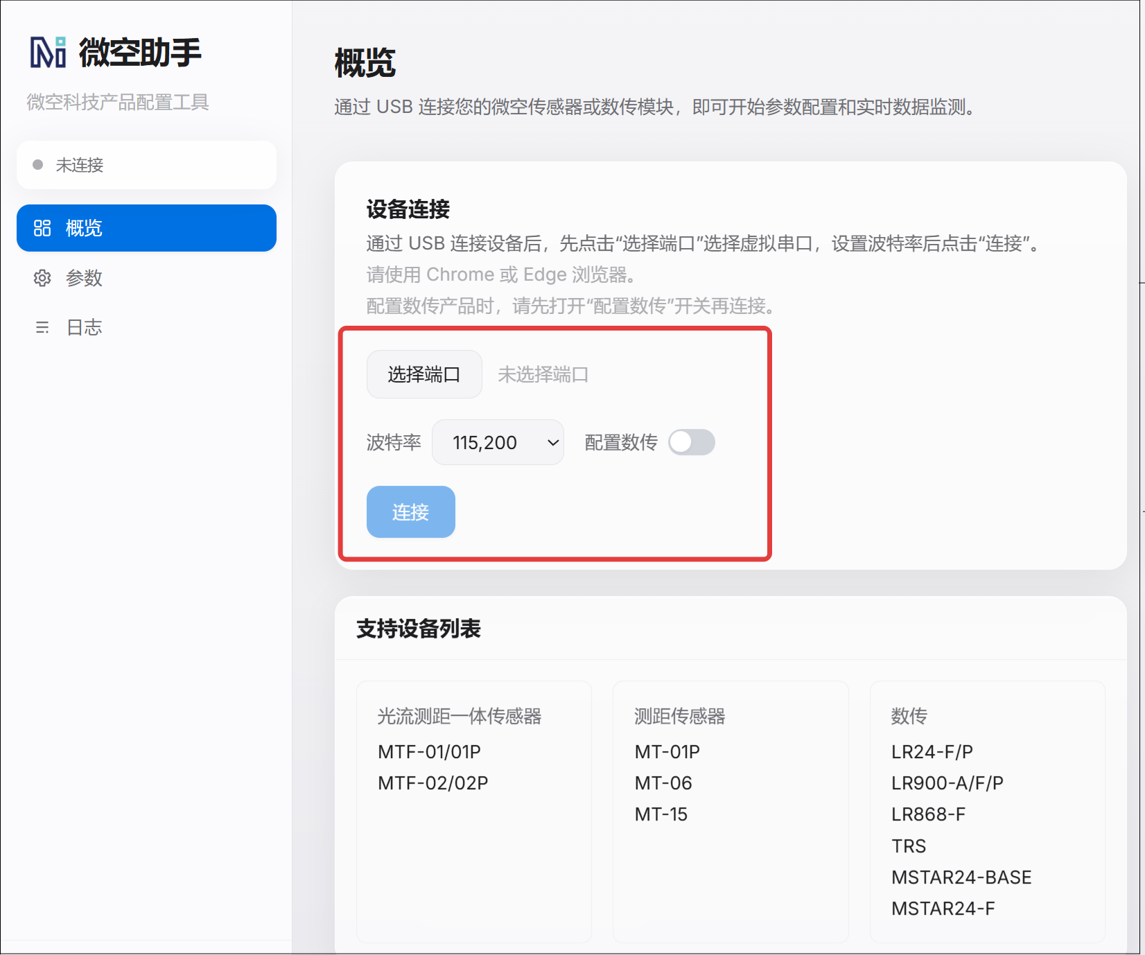
- When configuring a telemetry product, enable “Configure Telemetry” before connecting. The baud rate then changes automatically to the default telemetry configuration rate of
57600.
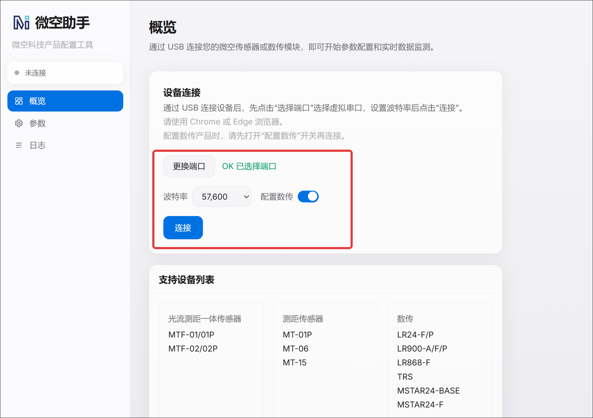
- Click “Connect.”
- Wait for the page to identify the device and display its model and related information.
If the page cannot identify the device, check the port, baud rate, driver, wiring, and power before changing any parameters.
Configuring Telemetry Radios with MicoAssistant
LR900, LR868, and LR24 Series
LR900, LR868, and LR24 telemetry radios are primarily used for point-to-point bidirectional communication. Read the ground-unit and air-unit parameters separately, and ensure that the communication settings match within each radio pair. The air unit's serial baud rate must also match the corresponding flight-controller port.
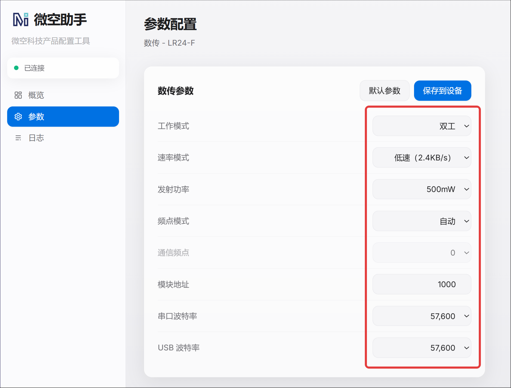
The LR24-F-Mini does not have a USB port for direct computer connection. To configure it, connect its UART interface through a USB-to-TTL adapter. Cross TX and RX, and ensure that both devices share ground.
For detailed parameter definitions, operating modes, wiring, and configuration procedures, see the appropriate product manual:
MSTAR24 Point-to-Multipoint Telemetry
MSTAR24 is a point-to-multipoint telemetry network consisting of one ground unit and one or more air units. Its firmware, operating modes, and parameter relationships differ from those of the LR900, LR868, and LR24 series. Do not apply the configuration method for conventional point-to-point telemetry radios directly.
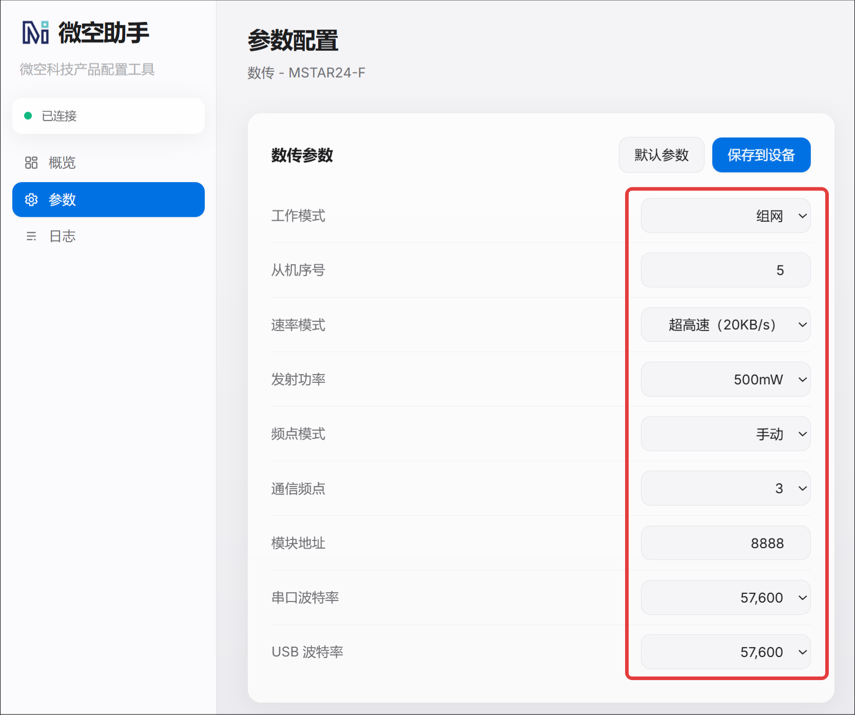
When the MSTAR24 ground unit connects to a computer, it creates 8 serial ports, ChA through ChH. ChA is also used to configure the ground unit. Each air unit must have a unique slave number and match the corresponding ground-unit channel. The module address, operating frequency, and rate mode must also correspond correctly across devices in the same system.
For complete wiring, driver installation, ground-unit and air-unit parameters, channel mapping, and multi-vehicle connection instructions, see:
TRS Integrated RC and Telemetry System
TRS is an integrated 2.4 GHz RC and telemetry system consisting of a transmitter module and a receiver. The transmitter uses a NANO interface and works with compatible OpenTX/EdgeTX radios. The receiver provides an SBUS control signal and a telemetry interface for flight controllers that support serial communication.
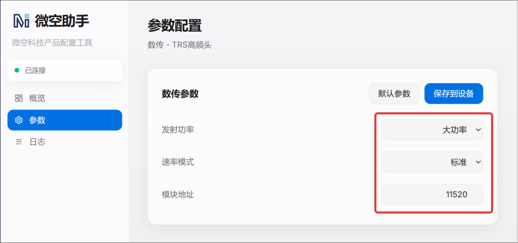
TRS provides long-range, standard, and high-speed operating modes, each with a different telemetry rate, RC update rate, and serial baud rate. The transmitter's operating mode and baud rate are linked. After binding, the receiver automatically adopts the telemetry baud rate associated with the transmitter's current mode, so the TRS receiver does not require separate parameter configuration.
For the TRS product overview, binding procedure, operating modes, connector definitions, Bluetooth connection, and complete configuration instructions, see:
Configuring Optical-Flow Sensors and Rangefinders with MicoAssistant
Read and Change Parameters
Confirm that the optical-flow and ranging module is wired correctly to the USB-to-TTL adapter before connecting through MicoAssistant.
- Connect the sensor to the computer.
- Set the baud rate to
115200in MicoAssistant. - Click “Select Port,” then choose the COM port that corresponds to the adapter in the browser dialog.
- Click “Connect,” and wait for the page to identify and display the device model.
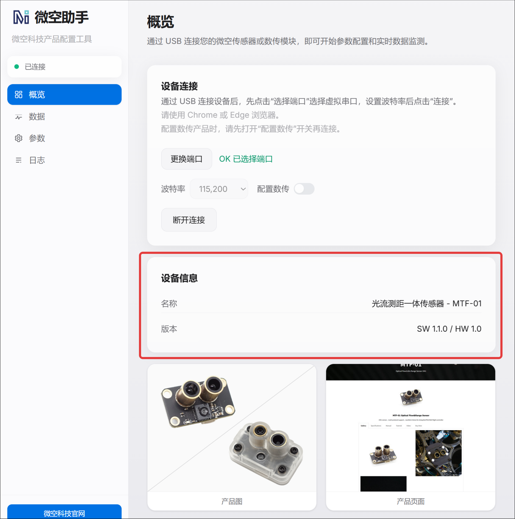
- Open the parameter settings page. MicoAssistant reads the module parameters automatically.
- Adjust the parameters as required.
- Click “Save to Device.”
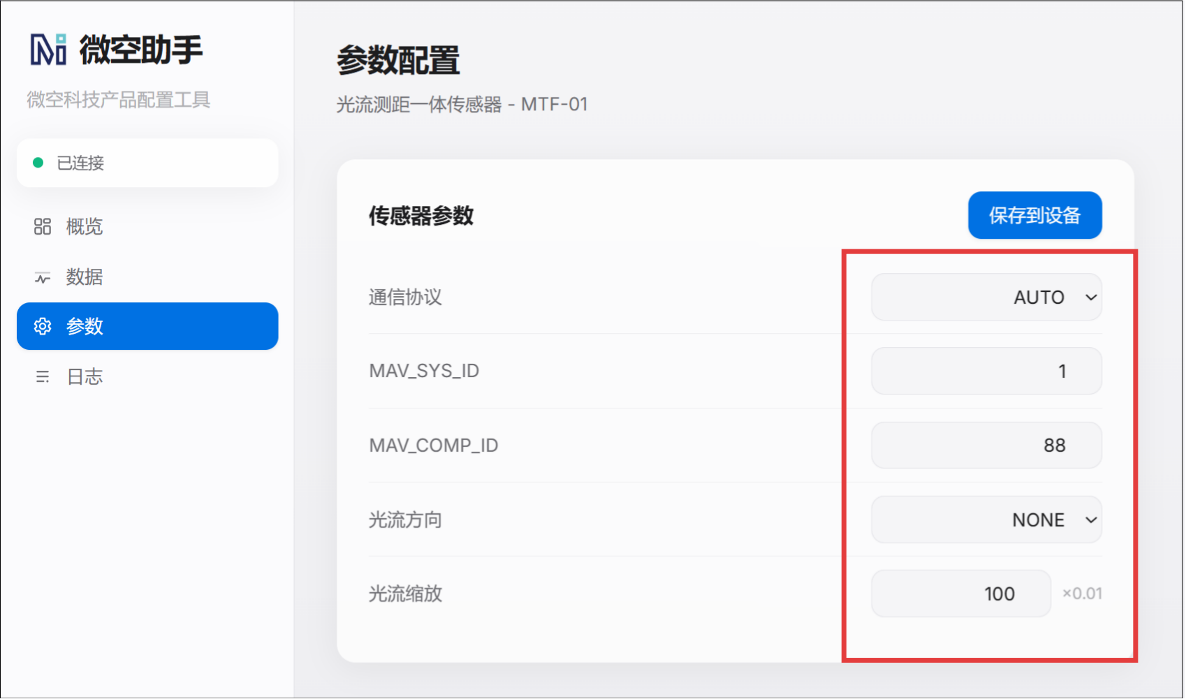
- Confirm that the parameters were written successfully. If necessary, power-cycle the device and read the parameters again to verify the changes.
For wiring, mounting orientation, flight-controller parameters, and product-specific usage instructions for MTF-series products, see the corresponding manuals:
- MTF-01 Optical Flow and Range Sensor User Manual
- MTF-01P Optical Flow and Range Sensor User Manual
- MTF-02/02P Optical Flow and Range Sensor User Manual
About the Auto Protocol
MTF-series firmware version 1.1.0 and later includes the Auto protocol, which automatically adapts the module to supported open-source autopilot firmware such as ArduPilot, PX4, and INAV. With Auto selected, users normally do not need to switch the module communication protocol manually in MicoAssistant, simplifying configuration and reducing disassembly.
Visualize Optical-Flow and Range Data
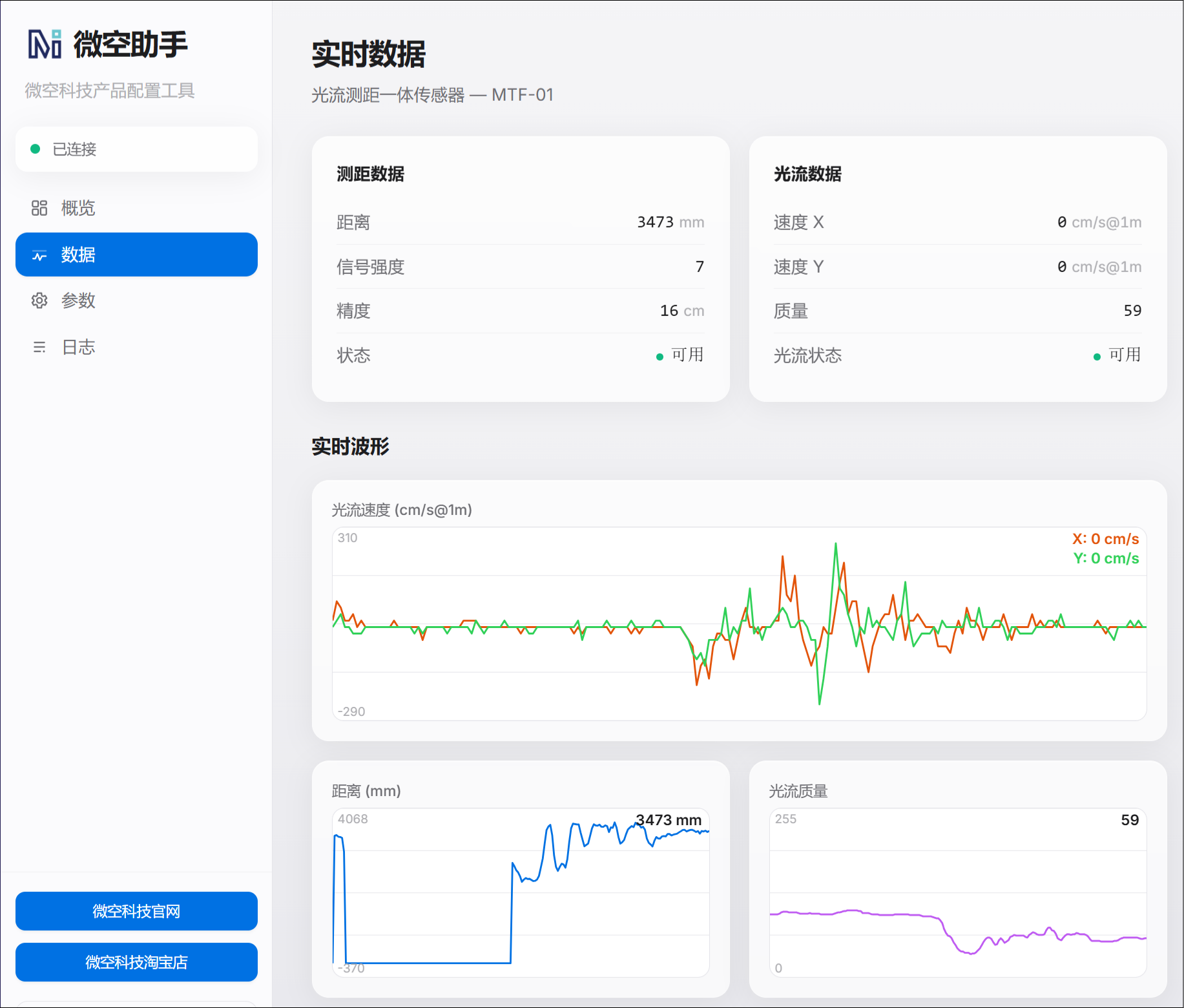
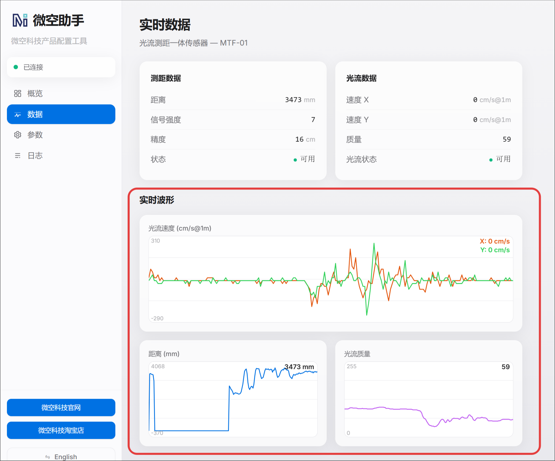
The “Data” page displays optical-flow and ranging-module output in real time. For MTF-series products, use the range value to verify that ranging works correctly. Move the module and observe whether the optical-flow velocity data changes accordingly to confirm that the output is correct and continuous and is not frozen or abnormal.
Troubleshooting
When troubleshooting MicoAssistant, check each layer in order: driver, port, physical connection, device identification, and finally parameters or data.
Driver Issues
The Computer Does Not Create a COM Port
If no new COM port appears in Windows Device Manager after connecting the device, check the following:
- The USB cable supports data transfer.
- The product or USB-to-TTL adapter is powered correctly.
- The USB port and wiring are reliable.
- The installed driver matches the USB-to-serial chipset.
Try another USB data cable or computer USB port, then reconnect the device. When using a USB-to-TTL adapter, select the driver for its CP210x, CH340/CH341, or FT232 chipset.
Device Manager Shows a Yellow Exclamation Mark or Unknown Device
A yellow exclamation mark or “Unknown device” generally indicates a missing driver, a driver installation problem, or an incorrect driver. Identify the USB-to-serial chipset, remove the problem device, reinstall the correct driver, and reconnect it.
If the device is still not recognized after the driver is installed, restart Windows and check Device Manager again.
Port and Browser Issues
No Ports Are Available in the Browser
- Use the latest version of Chrome or Edge.
- Confirm that the corresponding COM port appears in Windows Device Manager.
- Reconnect the device and refresh the MicoAssistant page.
- Check that the browser has permission to access serial ports.
- Avoid browsers that do not support Web Serial and avoid Incognito/InPrivate mode.
Port Access Is Denied or the Port Is Busy
Only one application can normally use a COM port at a time. Close Mission Planner, QGroundControl, serial-terminal tools, the desktop version of MicoAssistant, and any other software that might be using the port, then reconnect.
If the port still cannot be opened after closing these applications, reconnect the device. Restart the browser or computer if necessary.
The Selected Port Connects to the Wrong Device
When several serial devices are connected, the browser list may show multiple ports. Disconnect the target device and note which COM port disappears from Device Manager. Reconnect it and select the port that reappears.
Device Connection and Identification Issues
The Port Opens, but MicoAssistant Cannot Identify the Device
An open port only indicates that the browser has connected to the serial port; it does not confirm valid device communication. Check the following:
- The connection baud rate is correct.
- “Configure Telemetry” is enabled when configuring a telemetry product.
- TX and RX are crossed when using a USB-to-TTL adapter.
- Both devices share GND.
- The product supply voltage and serial logic level meet its requirements.
- The product is powered and running the correct firmware.
If the device model is not identified, the parameter settings page may not open or may not respond. Restore normal communication before reading or changing parameters.
The Device Disconnects Repeatedly
Check the USB cable, connector, and wiring for looseness, and confirm that the supply is stable. When using a USB-to-TTL adapter, ensure that it provides stable communication and is not connected through an unreliable USB expansion device.
Parameter Read and Save Issues
Device Parameters Cannot Be Read
- Confirm that MicoAssistant identifies the device model correctly.
- Check the port and baud rate.
- For telemetry products, confirm that “Configure Telemetry” is enabled.
- Close other software using the serial port.
- Disconnect and power-cycle the device, then reconnect.
Saved Parameters Do Not Take Effect
After saving parameters, confirm that the page reports a successful write. Restarting the device and reading the parameters again is recommended.
For telemetry products, also verify that paired settings such as module address, operating frequency, and operating mode match between the ground unit and air unit, and that the air unit's serial baud rate matches the corresponding flight-controller port.
Data Display Issues
No Data Appears on the Data Page
First confirm that the device is identified correctly, then verify that the “Data” page is open. If no data appears, check the baud rate, wiring, device power, and firmware version, then reconnect.
Range Values Are Abnormal or Do Not Change
Point the sensor at a flat target and vary the target distance within the valid measurement range. Avoid transparent surfaces such as glass, highly reflective surfaces such as mirrors, light-absorbing surfaces such as pure black materials, and surfaces at excessive angles. Also check that the ranging window is not obstructed or contaminated. When the rangefinder points into open space beyond its measurement range, the range value should be zero.
Optical-Flow Data Does Not Change or Is Abnormal
Point the optical-flow lens at a well-lit surface with clear texture. Move the module horizontally at an appropriate height and observe whether the optical-flow velocity data changes. Insufficient texture, low light, an obstructed lens, or excessive distance can cause abnormal optical-flow data.
If the data remains frozen, jumps significantly, or stays at zero, check the device connection, power, and parameter settings again, then power-cycle the device and retest.