

Docs directory
Table of contents
MSTAR24 One-to-Many Telemetry Configuration and Usage Guide
This guide explains how to configure MSTAR24 telemetry radios for one-to-many multi-vehicle connections. It covers ground unit and air unit setup, ArduPilot and PX4 flight controller parameters, and Mission Planner/QGroundControl connection examples so multiple vehicles can be connected and monitored from one ground control station.
Telemetry Wiring and Driver Installation
Air Unit Telemetry Wiring
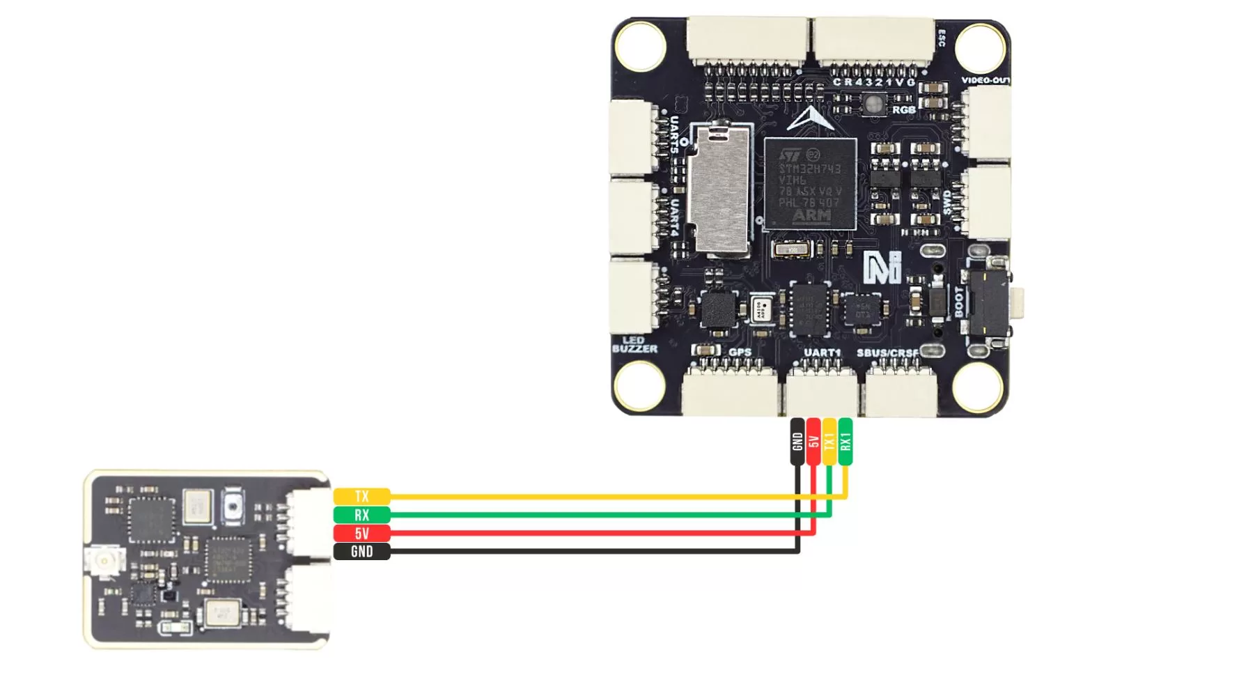
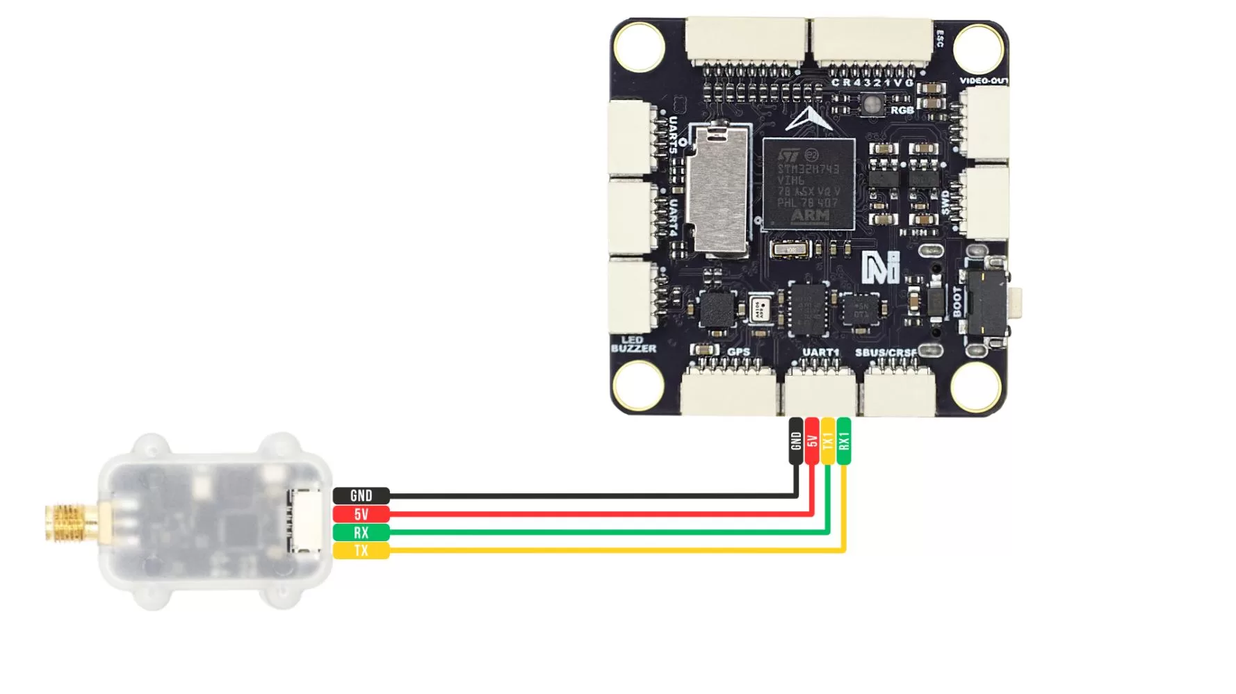
The MSTAR24 telemetry air unit must be correctly connected to a serial port on the flight controller, such as TELEM1 (Serial1). Pay attention to the following wiring rules:
- Connect telemetry TX to flight controller RX
- Connect telemetry RX to flight controller TX
MSTAR24-F-Mini wiring diagram:
MSTAR24-F wiring diagram:
Telemetry Driver Installation
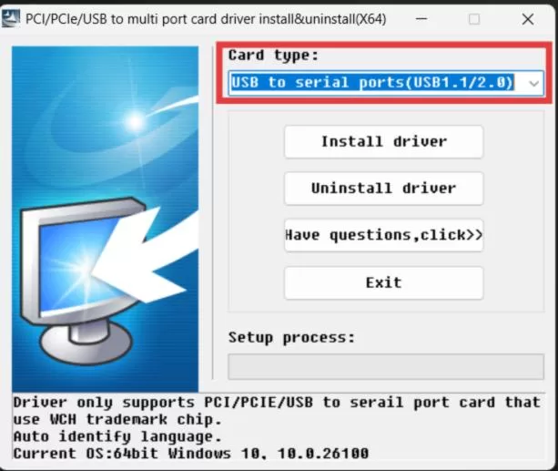
Download and extract the driver package. Double-click the installer, select “USB to Multi-Serial Port”, and click Install Driver. The driver will be installed automatically after a short wait.
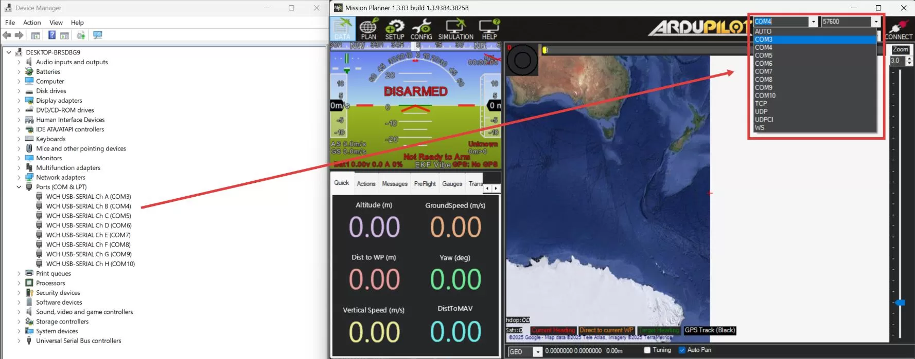
After the driver is installed, connect the MSTAR24 telemetry ground unit to the computer using a USB cable. Open Windows Device Manager. You should see eight serial ports, from ChA to ChH. The COM port numbers are assigned automatically by Windows and may vary between computers.
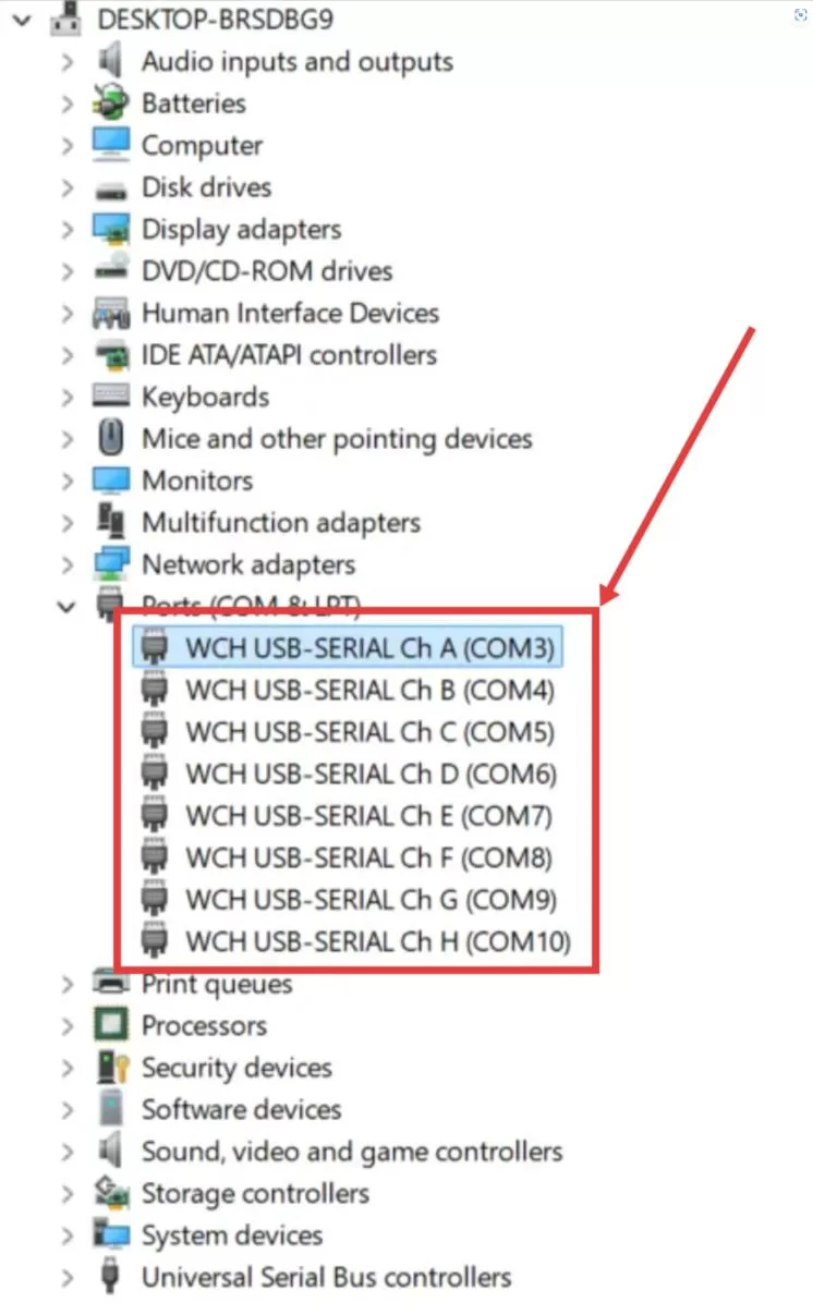
ChA corresponds to air unit channel 0 and is also used to configure the ground unit parameters. ChB corresponds to air unit channel 1, ChC corresponds to air unit channel 2, and so on. The system supports up to ChH, which corresponds to air unit channel 7. If the computer detects only one serial port, or if ChA to ChH are not displayed, check whether the driver is correctly installed, whether the USB cable supports data transfer, whether the connected device is an MSTAR24 ground unit, and whether Device Manager shows any yellow warning icons.
Telemetry Parameter Configuration
Ground Unit Configuration
Connect the ground unit module to the computer, open Device Manager, and note the COM port corresponding to ChA.
Open the MicoAssistant software (version 0.9.16 or later), select the COM port identified above, set the baud rate to 57600, and click Connect. Then click the radio icon on the right side to open the telemetry settings page. The host software will automatically identify the module and display the parameter configuration page. Click Read Settings to retrieve the parameters stored in the telemetry module, and click Write Settings to write the current page settings to the telemetry module.
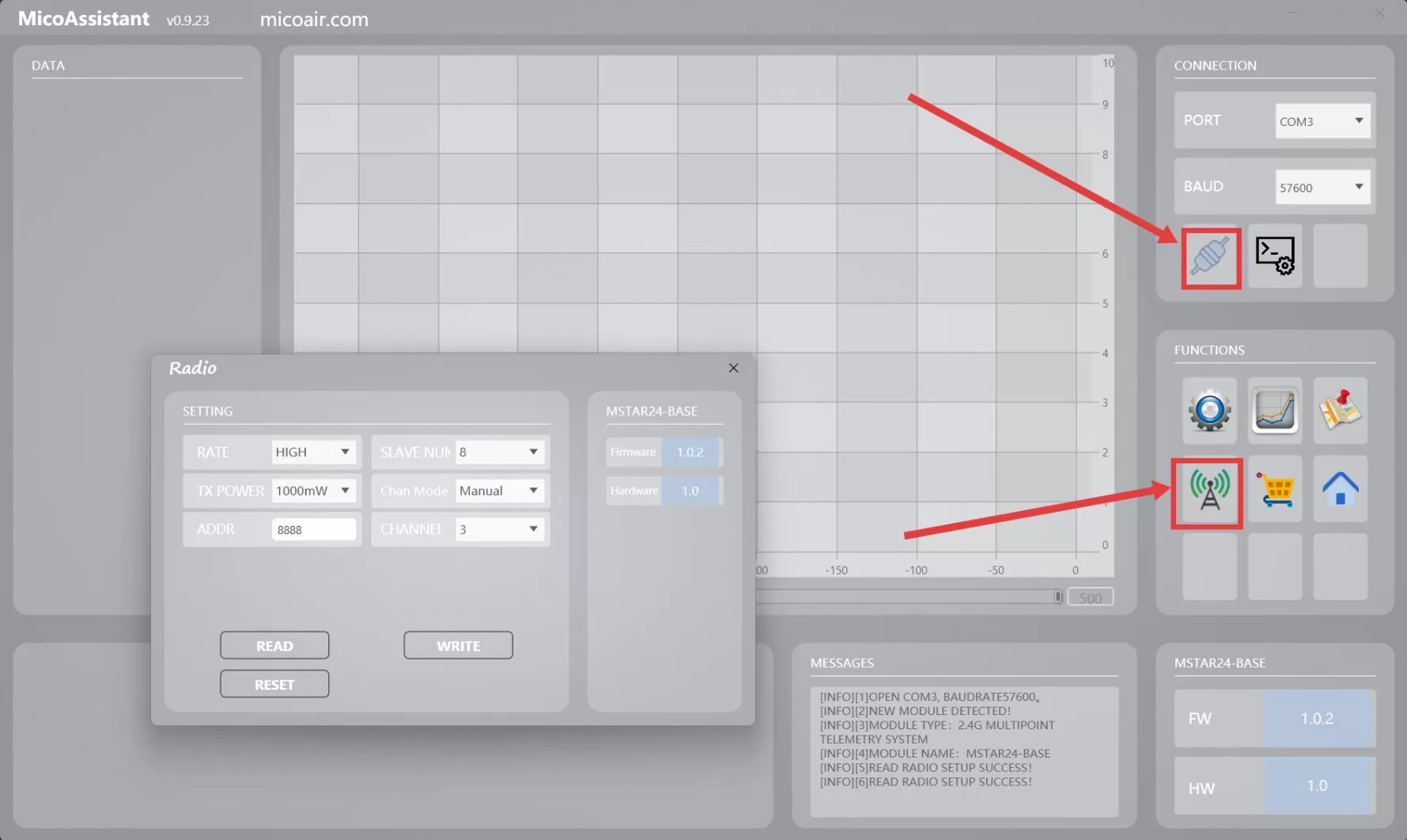
Ground Unit Parameter
| Parameter | Description | Recommendation |
|---|---|---|
| Rate Mode | Standard mode is the default mode. In this mode, the total downlink throughput for all air units is 10.5KB/s. In high-speed mode, the total downlink throughput for all air units is 22KB/s. | Use high-speed mode when connecting many vehicles or when the data volume is relatively large. |
| Number of Slave Units | Sets the number of air units. The range is 1-8, and the default value is 4. The more air units are configured, the less bandwidth each air unit receives. | Set this according to the actual number of connected air units. |
| Transmit Power | Sets the transmit power of the ground unit. The default maximum value is 1000mW. | Usually keep the default setting. |
| Frequency Mode | Fixed to manual mode. | Keep the default setting. |
| Module Address | Only ground units and air units with the same module address can connect and communicate. The range is 1-30000, and the default value is 8888. | Keep this consistent within the same telemetry group. Use different addresses when multiple telemetry sets are used at the same time. |
| Communication Frequency | Operating frequency of the telemetry radio. The range is 0-82, corresponding to 2400-2482MHz, and the default value is 0. | Keep this consistent within the same telemetry group. When multiple telemetry sets are used at the same time, use different frequency points where possible. |
Rate allocation example: if the number of slave units on the ground unit is set to 4 and standard mode is used, each air unit receives a downlink rate of approximately 10.5KB/s / 4 = 2.625KB/s.
Air Unit Configuration
MSTAR24 supports multiple air unit hardware versions, such as MSTAR24-F-Mini and MSTAR24-F. This section uses MSTAR24-F as an example to explain the configuration procedure.
The MSTAR24-F has an onboard CP2102 USB-to-serial chip. Refer to the CP2102 Driver Installation Guide (Windows) to install the CP2102 driver.
Connect the telemetry air unit to the computer, open Device Manager, and note the COM port corresponding to the CP2102 device.
Open the MicoAssistant software (version 0.9.16 or later), select the COM port identified above, set the baud rate to 57600, and click Connect.
Click the radio icon on the right side to open the telemetry settings page. The host software will automatically identify the module and display the parameter configuration page. Click Read Settings to retrieve the parameters stored in the telemetry module, and click Write Settings to write the current page settings to the telemetry module.
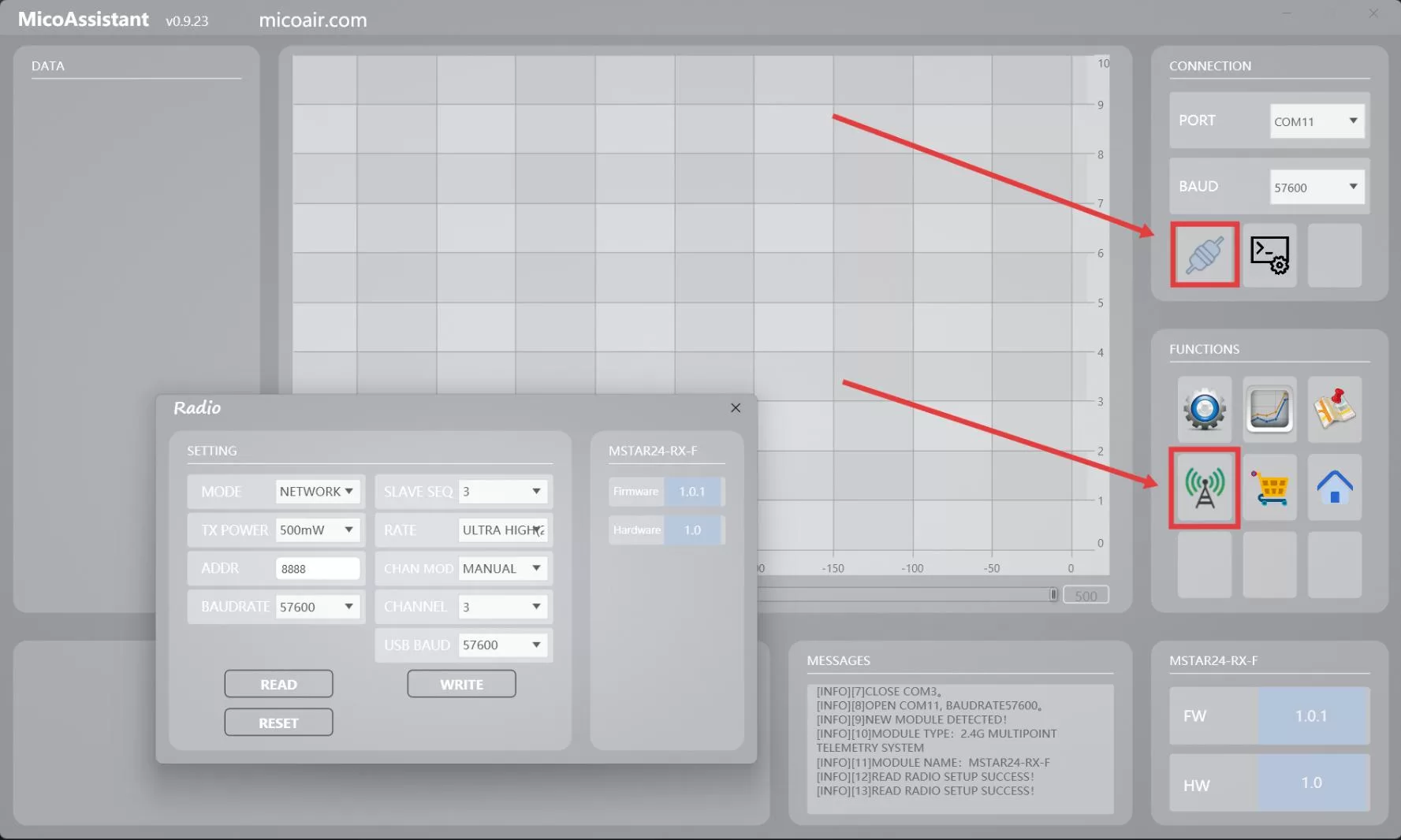
In addition to being used as a slave unit in one-to-many mode, the air unit can also be configured as a standard telemetry radio for one-to-one or one-to-N broadcast use. This document only describes the basic configuration required when using the air unit as a one-to-many slave unit.
Air Unit Parameters
| Parameter | Description | Recommendation |
|---|---|---|
| Operating Mode | When used as a one-to-many slave unit, networking mode must be selected. This is the default mode. | Keep networking mode enabled. |
| Slave Unit ID | Used to distinguish different air units. The range is 0-7, and the default value is 0. For example, in a one-to-three setup, the three air units should be set to 0, 1, and 2. | Each air unit must use a different value. It is recommended to assign values consecutively starting from 0. |
| Transmit Power | The maximum transmit power of MSTAR24-F/F-Mini is 500mW. | Usually keep the default setting, or adjust it based on the actual operating distance. |
| Rate Mode | When used as a one-to-many slave unit, only high-speed mode and ultra-high-speed mode are available. Air unit high-speed mode corresponds to ground unit standard mode. Air unit ultra-high-speed mode corresponds to ground unit high-speed mode. | If the ground unit is in standard mode, set the air unit to high-speed mode. If the ground unit is in high-speed mode, set the air unit to ultra-high-speed mode. |
| Module Address | Only telemetry modules with the same module address can connect and communicate. The range is 1-30000, and the default value is 8888. | Must be the same as the ground unit. |
| Frequency Mode | When used as an air unit slave, this must be set to manual mode. Manual mode is the default setting. | Keep the default setting. |
| Communication Frequency | Operating frequency of the telemetry radio. The range is 0-82, corresponding to 2400-2482MHz, and the default value is 0. | Must be the same as the ground unit. |
| Serial Baud Rate | Baud rate of the serial port on the GH1.25 connector. The default value is 57600. | Must match the baud rate of the corresponding flight controller serial port. |
| USB Baud Rate | Baud rate of the USB serial interface. The default value is 57600. | Usually keep the default setting. |
Mapping Between Air Unit Slave IDs and Ground Unit Channels
The correspondence between air unit slave IDs and ground unit serial channels is as follows:
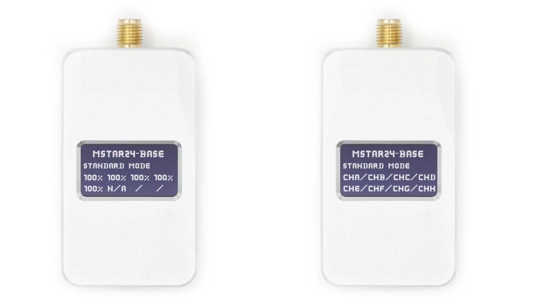
| Air Unit Slave ID | Ground Unit Channel | Example Use |
|---|---|---|
0 | ChA | Vehicle 1 |
1 | ChB | Vehicle 2 |
2 | ChC | Vehicle 3 |
3 | ChD | Vehicle 4 |
4 | ChE | Vehicle 5 |
5 | ChF | Vehicle 6 |
6 | ChG | Vehicle 7 |
7 | ChH | Vehicle 8 |
Flight Controller Configuration
When connecting multiple vehicles, each flight controller must use a different system ID. Otherwise, the ground control station cannot correctly distinguish between multiple vehicles.
ArduPilot Parameter Setup
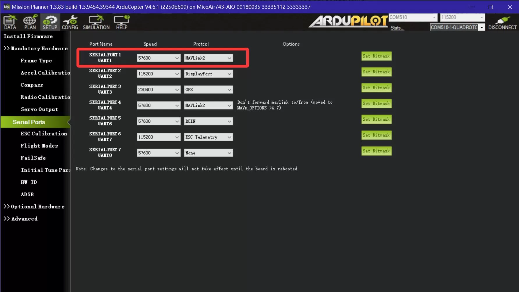
Connect the flight controller to the computer using USB, open Mission Planner, and connect to the flight controller. If the telemetry air unit is connected to the TELEM1 (Serial1) port on the flight controller, set the following parameters:
SERIAL1_BAUD = 57600
SERIAL1_PROTOCOL = MAVLink2
If the air unit is connected to another serial port, configure the corresponding SERIALx_BAUD and SERIALx_PROTOCOL parameters.
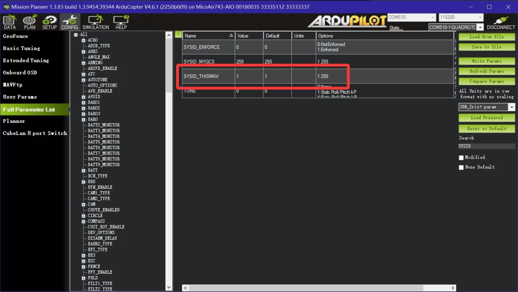
Then connect each ArduPilot flight controller individually and set SYSID_THISMAV:
- Flight controller 1:
SYSID_THISMAV = 1 - Flight controller 2:
SYSID_THISMAV = 2 - Flight controller 3:
SYSID_THISMAV = 3 - Continue in the same way for additional flight controllers
PX4 Parameter Setup
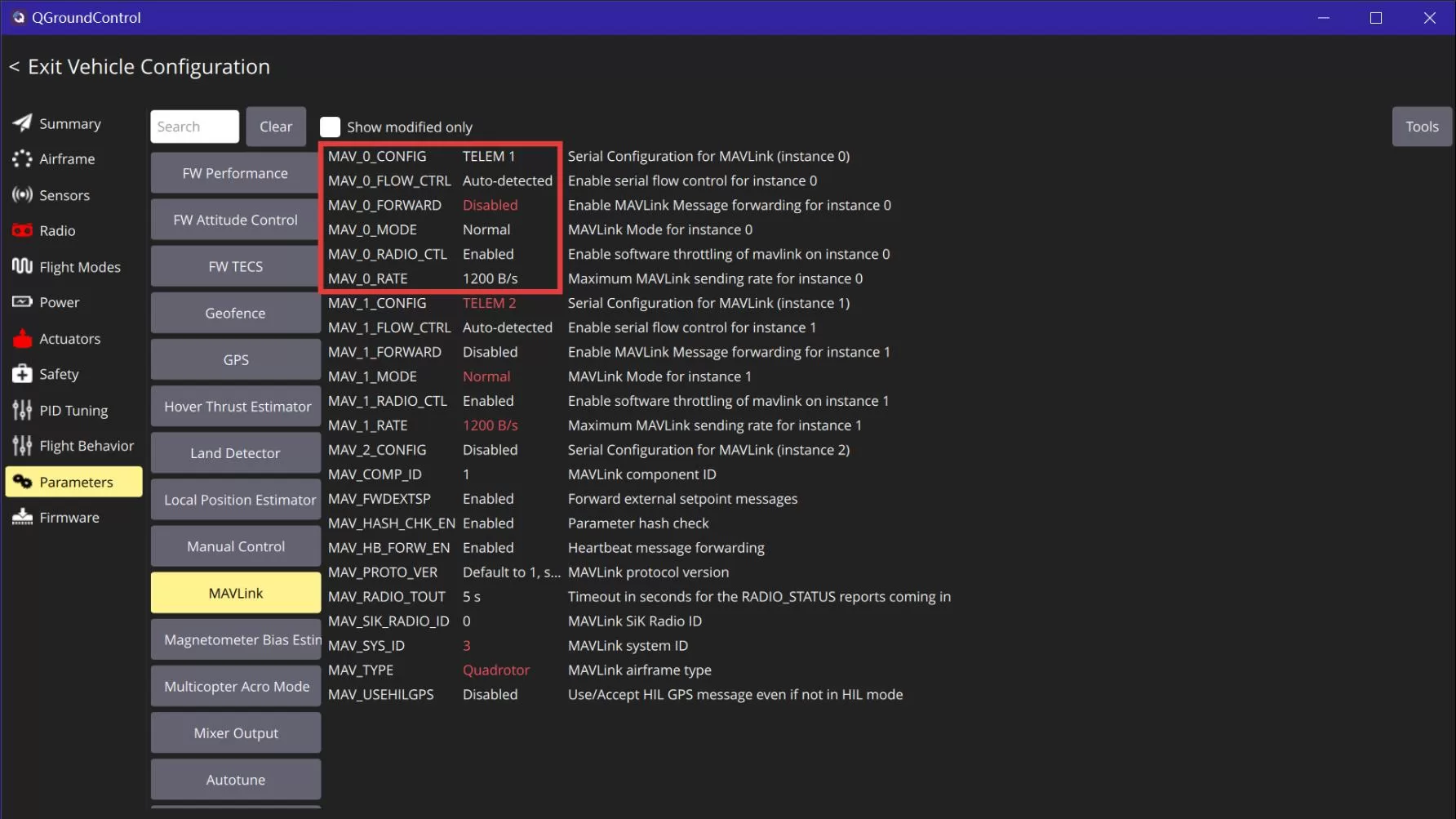
Connect the flight controller to the computer using USB, open QGroundControl, and connect to the flight controller. On the parameter page, locate MAVLink. If the telemetry air unit is connected to TELEM1, configure the following:
MAV_0_CONFIG = TELEM1
MAV_0_FORWARD = Disabled
MAV_0_MODE = Normal
MAV_0_RATE = 1200B/s
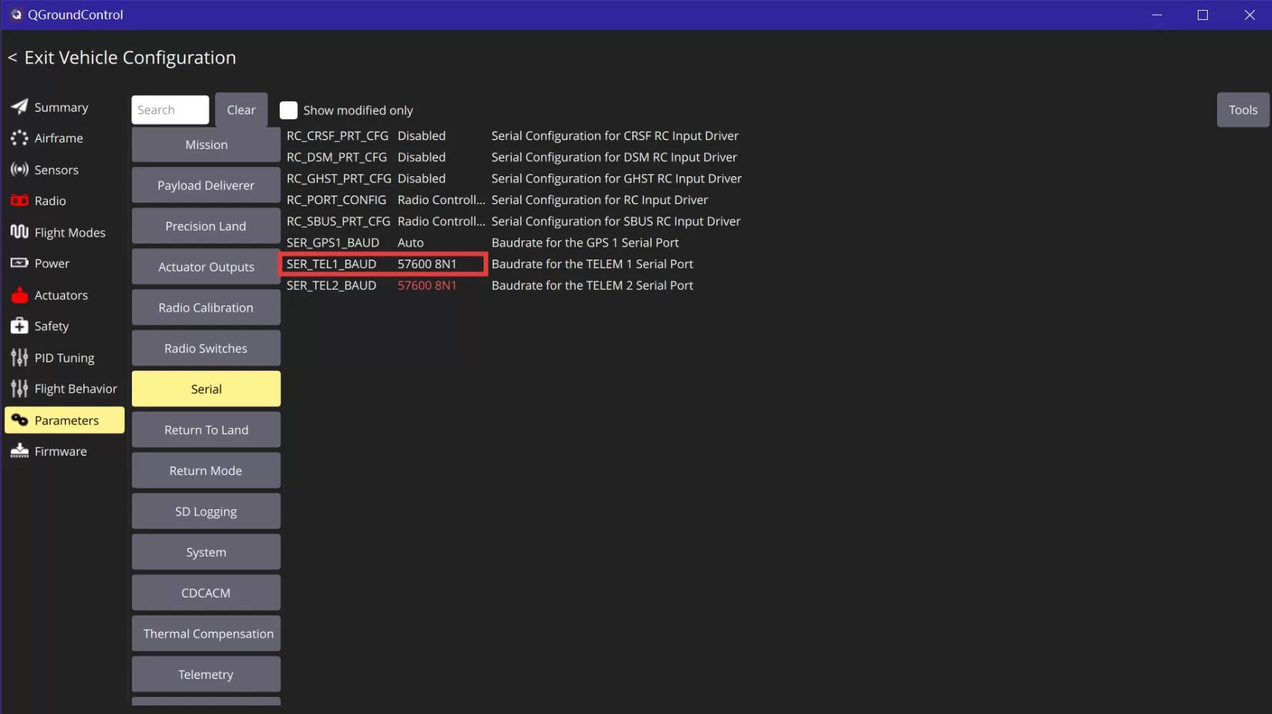
After saving the parameters, restart the flight controller and reconnect. On the parameter page, locate the serial port settings and set:
SER_TEL_1_BAUD = 57600 8N1
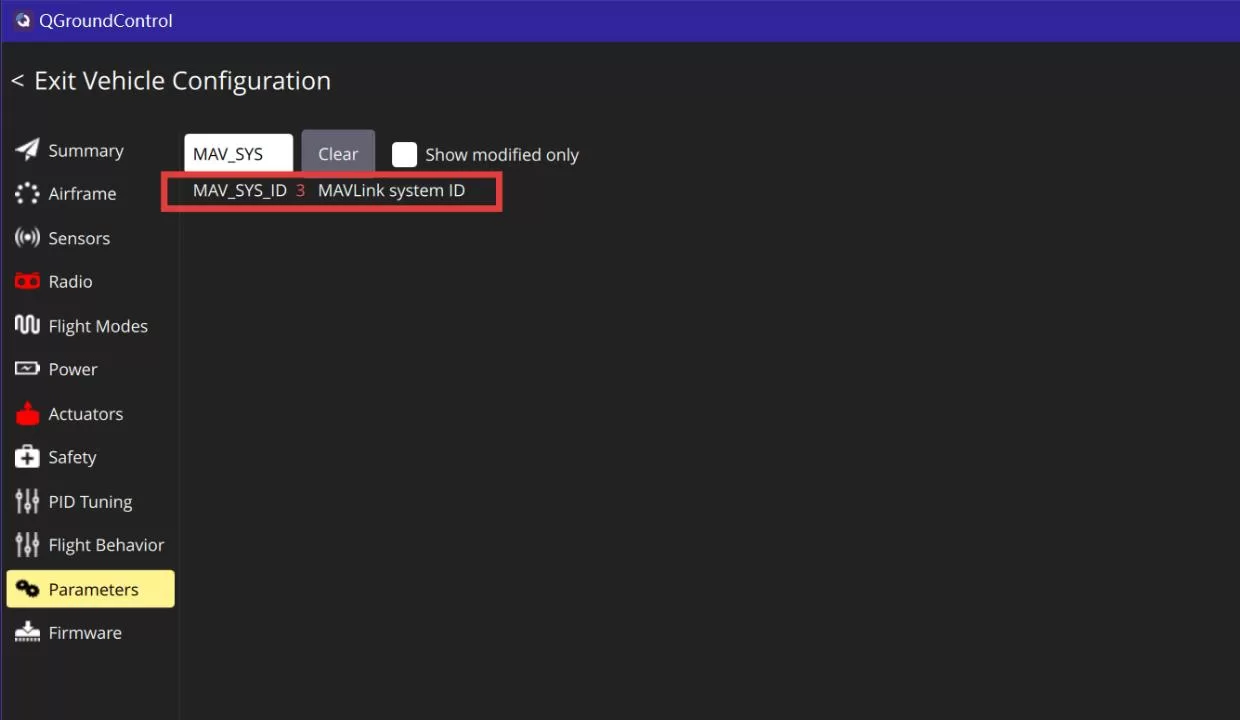
Multiple PX4 flight controllers must use different system IDs. Otherwise, QGroundControl cannot identify multiple vehicles correctly. Connect each flight controller individually using USB and modify MAV_SYS_ID in QGroundControl:
- Flight controller 1:
MAV_SYS_ID = 1 - Flight controller 2:
MAV_SYS_ID = 2 - Flight controller 3:
MAV_SYS_ID = 3 - Continue in the same way for additional flight controllers
If only one vehicle can be connected, or if the ground control station identifies vehicles incorrectly, focus on checking whether each air unit uses a different slave ID, whether each flight controller uses a different system ID, and whether the flight controller serial parameters match the telemetry serial baud rate.
Multi-Vehicle Connection Example
After completing the ground unit, air unit, and flight controller configuration, you can connect multiple vehicles through the ground control station software. Before connecting, confirm the following:
- The ground unit is connected to the computer via USB
- Each air unit is connected to the corresponding flight controller and powered on
- Each air unit uses a different slave ID
- Each flight controller uses a different MAVLink system ID
- The module address and communication frequency are the same between the ground unit and all air units
- The rate modes of the ground unit and air units correspond correctly
If the air units are correctly connected to the ground unit, the green LED on each air unit will remain steadily on, and the display on the ground unit will show the signal strength of the corresponding channel.
ArduPilot Multi-Vehicle Connection
Using a one-to-three setup as an example, one ground unit is connected to the computer, and three air units are connected to three vehicles respectively. After completing the telemetry configuration described above, set the slave IDs of the three air units to 0, 1, and 2. Air unit 0 connects to flight controller 1, air unit 1 connects to flight controller 2, and air unit 2 connects to flight controller 3. Set SYSID_THISMAV on the three flight controllers to 1, 2, and 3 respectively. Open Mission Planner. In the connection area in the upper-right corner, select the COM port corresponding to ChA, set the baud rate to 57600, and click “Connect”. This connects to vehicle 1 through air unit 0.
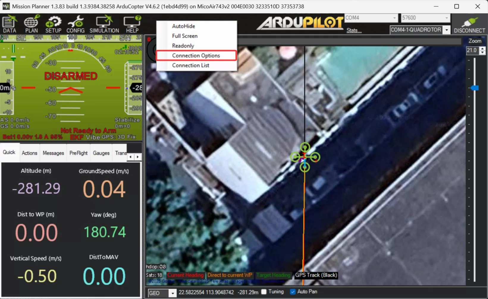
After vehicle 1 is connected successfully, right-click the black area on the top toolbar in Mission Planner and select the connection option.
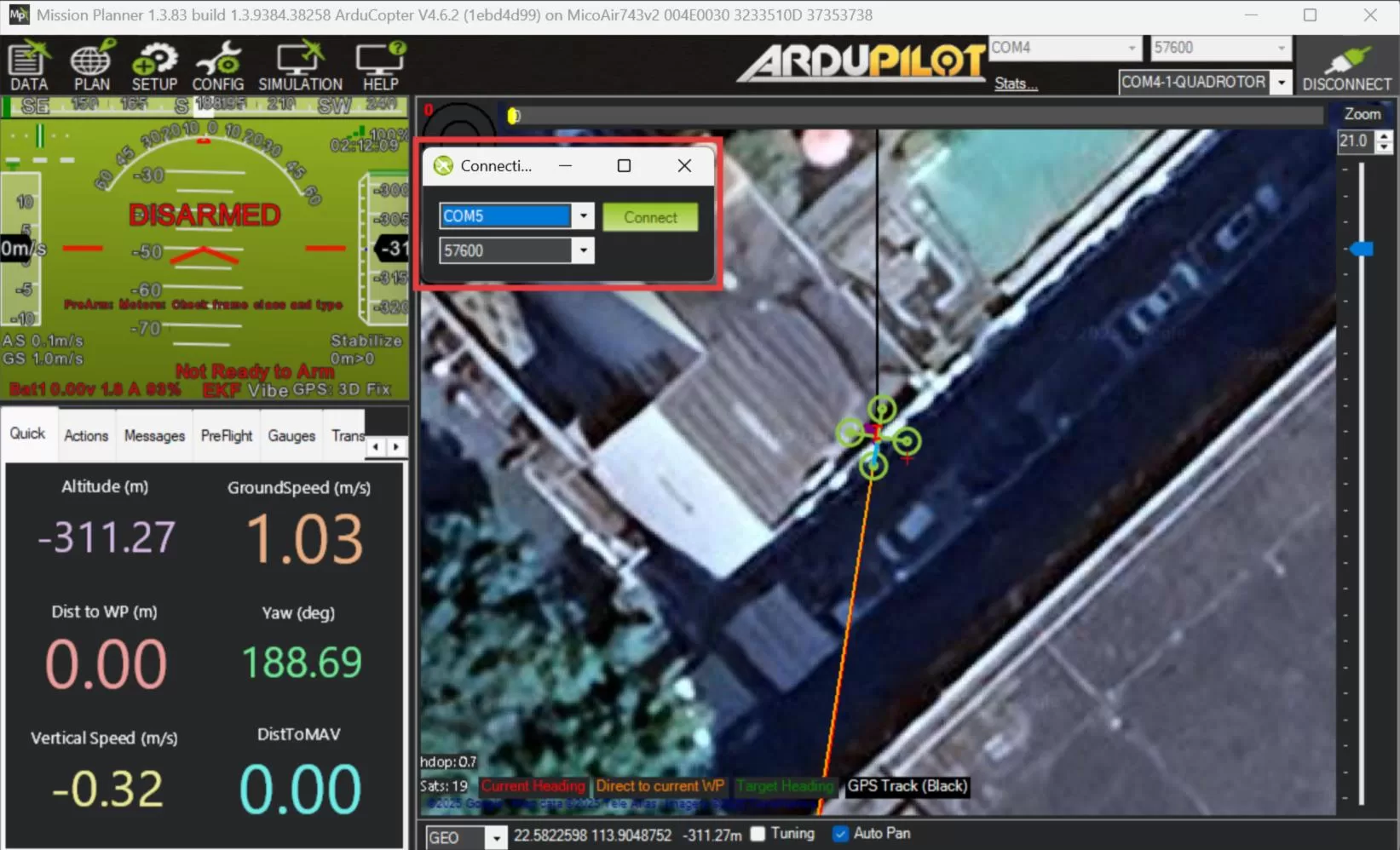
In the pop-up connection window, select the COM port corresponding to ChB, set the baud rate to 57600, and click “Connect”. Vehicle 2 will then connect to Mission Planner.
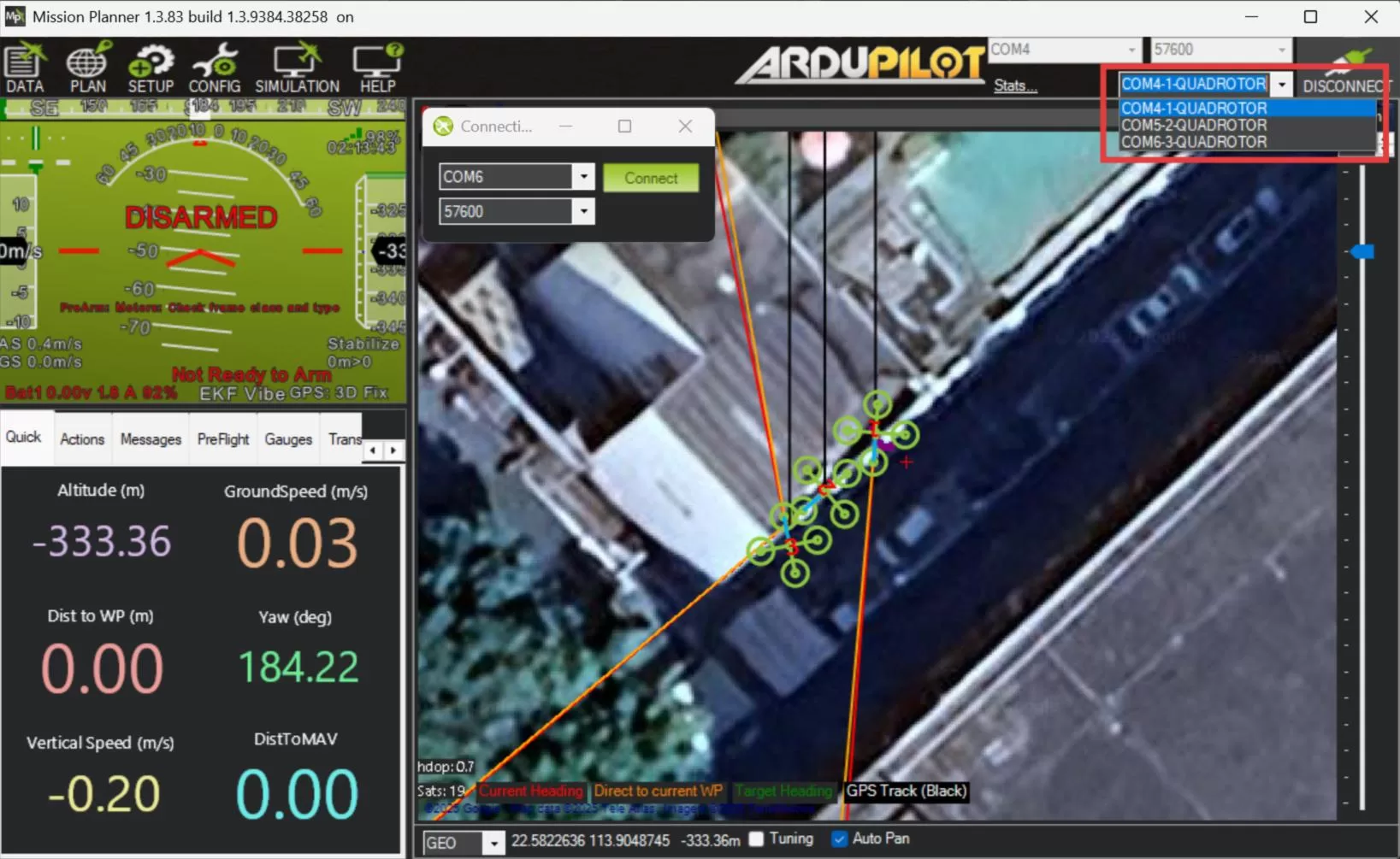
Connect vehicle 3 and any additional vehicles in the same way. If using a one-to-five or one-to-eight setup, add connections in sequence according to ChA, ChB, ChC, ChD, and so on.
After the connections are complete, if the vehicles are outdoors and have obtained a GPS position, you can view the real-time positions of multiple vehicles on the map on the right side of Mission Planner.
PX4 Multi-Vehicle Connection
Using a one-to-three setup as an example, one ground unit is connected to the computer, and three air units are connected to three vehicles respectively. Set the slave IDs of the three air units to 0, 1, and 2. Set MAV_SYS_ID on the three PX4 flight controllers to 1, 2, and 3 respectively.
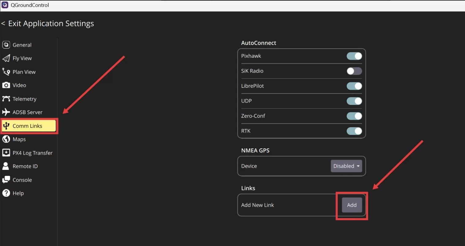
Open QGroundControl, go to the communication link page, and click “Add” to create a new connection profile.
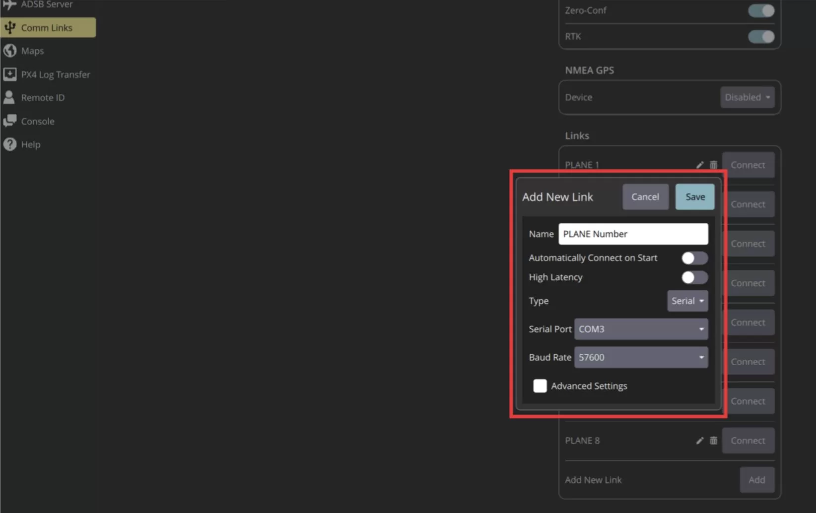
Name the first connection profile “Vehicle 1”, select the COM port corresponding to ChA, set the baud rate to 57600, and click “Save”.
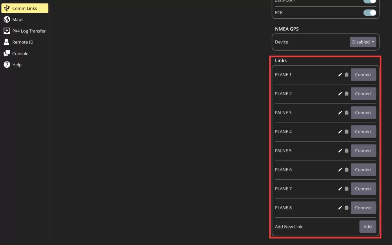
Add “Vehicle 2”, “Vehicle 3”, and other connection profiles in the same way, selecting the corresponding serial ports such as ChB and ChC.
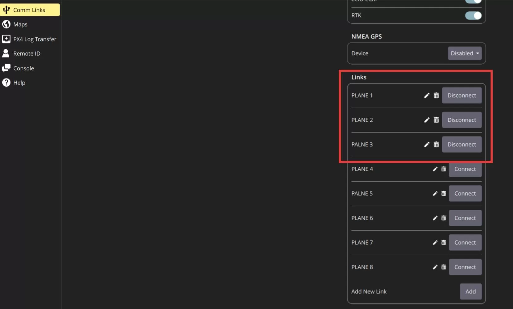
Select the multiple profiles that need to be connected, for example “Vehicle 1” through “Vehicle 3”, and click “Connect”. QGroundControl will connect to all three vehicles at the same time. Reading parameters may take 1 to 2 minutes.
After the connection is complete, you can select the multi-vehicle view in the upper-right corner to view the status and instrument information of all connected vehicles.
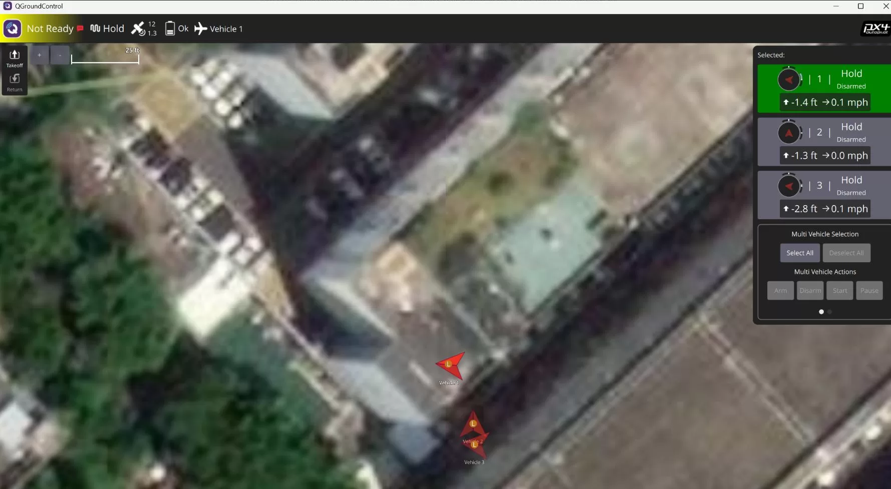
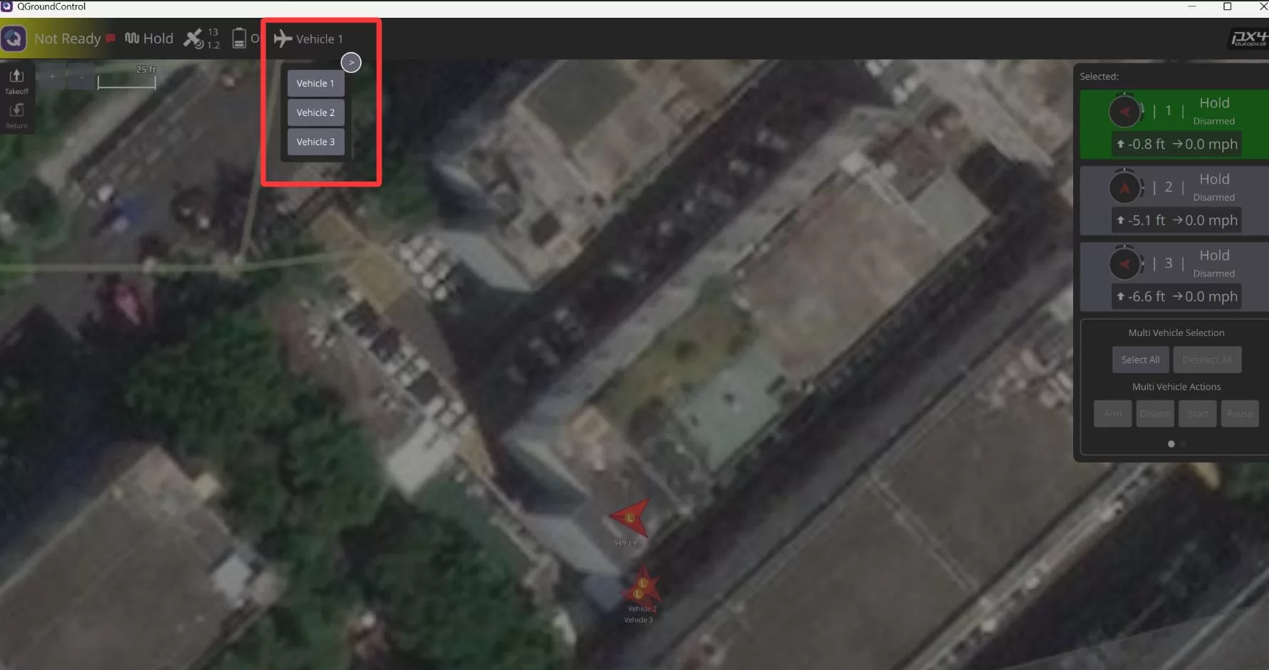
You can also switch between different vehicles from the toolbar and perform operations such as parameter configuration and mission planning for each vehicle individually.
If the ground control station connects slowly, reads parameters slowly, or has high latency, this is usually because all air units share the total downlink bandwidth of the ground unit in one-to-many mode. The more slave units are configured, the less bandwidth each vehicle receives. You can try setting the number of slave units on the ground unit to the actual number in use, using a higher rate mode while ensuring that the air unit rate mode matches correctly, or reducing the MAVLink data stream rate from the flight controller.
Additional Reference
How to Connect Multiple Vehicles in Mission Planner for Drone Swarming?