
Docs directory
Table of contents
MicoAir-WiFi-Link Dual-Band Wi-Fi 6 Telemetry Module User Manual
Product Overview
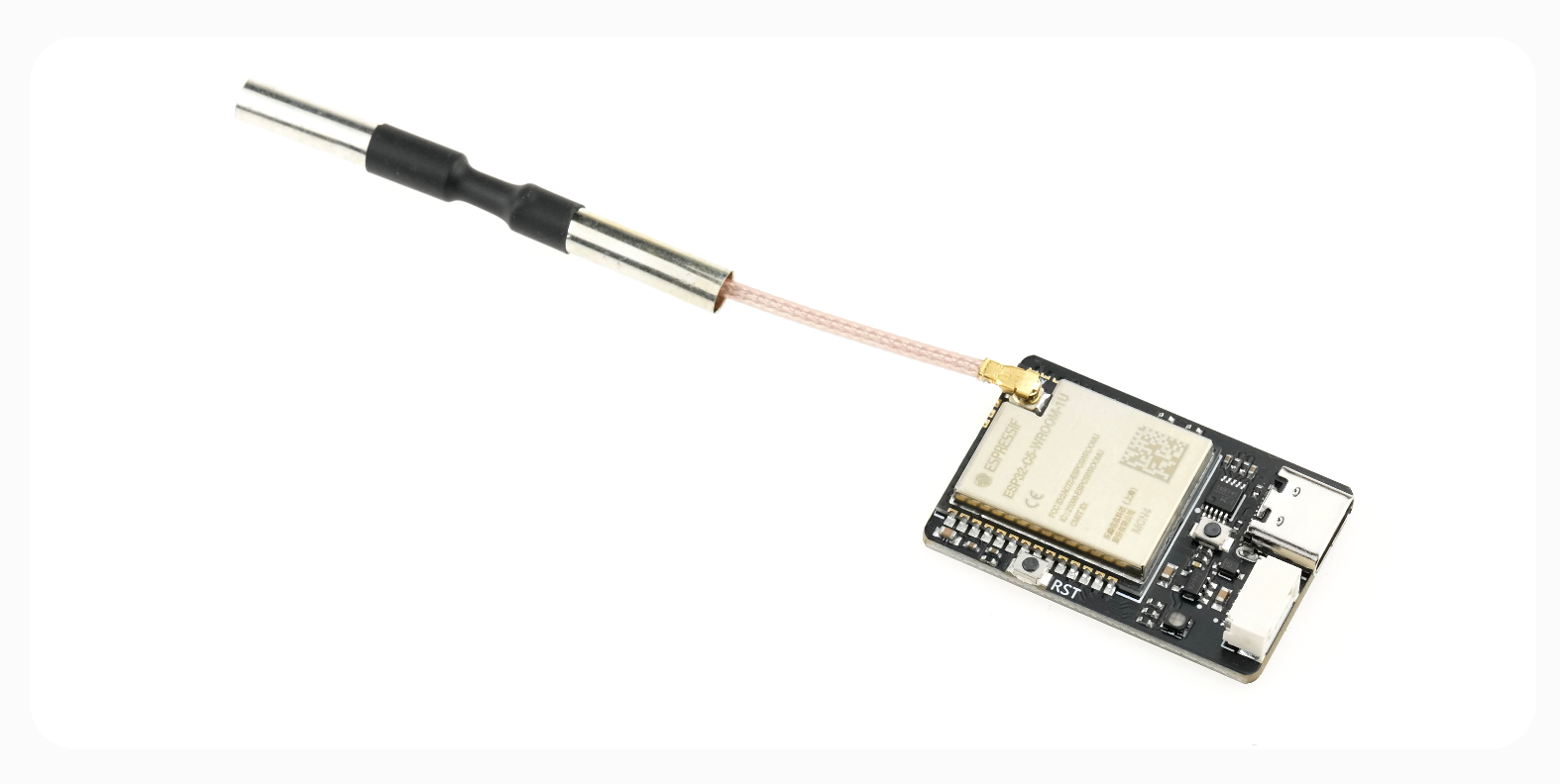
MicoAir-WiFi-Link is a dual-band Wi-Fi 6 telemetry module developed by MicoAir for wireless data links in drones and robots. It can be used for wireless flight-controller configuration, telemetry transmission, and multi-device networking and commissioning for drone light shows. OFDMA and downlink MU-MIMO improve concurrent transmission efficiency and make multi-device wireless connections more reliable.
Purchase
Typical Applications
MicoAir-WiFi-Link is suitable for the following applications:
-
Wireless configuration of open-source flight controllers running ArduPilot or PX4, with support for ground control station (GCS) software such as Mission Planner, QGroundControl, and MicoPilot
-
Multi-device networking for drone-light-show formations, including network connections and the upload of routes and commands, with Skybrush support
-
Wireless access for robots and unmanned systems that require short-range, high-throughput wireless communication for control and commissioning
Features
- Based on
ESP32-C5 - Dual-band Wi-Fi:
2.4 GHz / 5 GHz - Supports
Wi-Fi 6 (802.11ax)and is backward compatible with 802.11 a/b/g/n/ac - Direct connection through
APmode by default - Supports
STAmode for connecting to a router - Supports bidirectional
UART <-> UDPpassthrough - BLE UART passthrough (currently supported only by MicoPilot)
- Browser-based configuration
- USB UART configuration using AT commands
- Firmware upgrade through MicoAssistant
Technical Specifications
Core Specifications
| Item | Specification |
|---|---|
| Main platform | ESP32-C5 |
| Wireless standard | Wi-Fi 6 / 802.11ax, backward compatible with 802.11 a/b/g/n/ac |
| Frequency bands | 2.4 GHz / 5 GHz |
| Communication interfaces | LVTTL (3.3 V) UART / USB Type-C (CH340) |
| Core functions | Wi-Fi UDP-to-UART passthrough / BLE UART passthrough (BLE connections currently supported only by MicoPilot) |
| Default Wi-Fi operating mode | AP (can be switched to STA mode using AT commands) |
| Maximum communication distance (AP mode) | 100 m (phone or computer connected directly, measured in an unobstructed, interference-free environment) |
| Maximum communication distance (STA mode) | 500 m (forwarded through a high-power router, measured in an unobstructed, interference-free environment) |
| Maximum BLE communication distance | 10 m |
| Supply voltage | 5 V |
| Average operating current | 150 mA |
| Module dimensions | 34.5 × 23.5 × 6 mm |
| Module weight | 5.5 g (excluding antenna) |
UART Parameters
| Item | Specification |
|---|---|
| Debug UART baud rate | 115200 |
| Passthrough UART baud rate | 57600 / 115200 (default) / 230400 / 460800 / 921600 |
The default MicoAir-WiFi-Link passthrough UART baud rate is
115200. Configure the connected flight-controller UART to the same baud rate; otherwise, telemetry communication will not work.
Default Network Parameters
| Item | Default value |
|---|---|
| AP SSID | MicoAir_WiFi_Link_XXXX |
| AP password | 12345678 |
| AP gateway (configuration-page address) | 192.168.4.1 |
| STA local IP | 192.168.1.101 |
| STA target IP | 192.168.1.2 |
| STA gateway | 192.168.1.1 |
| UDP port | 14550 |
Wi-Fi Operating Modes
| Mode | Description |
|---|---|
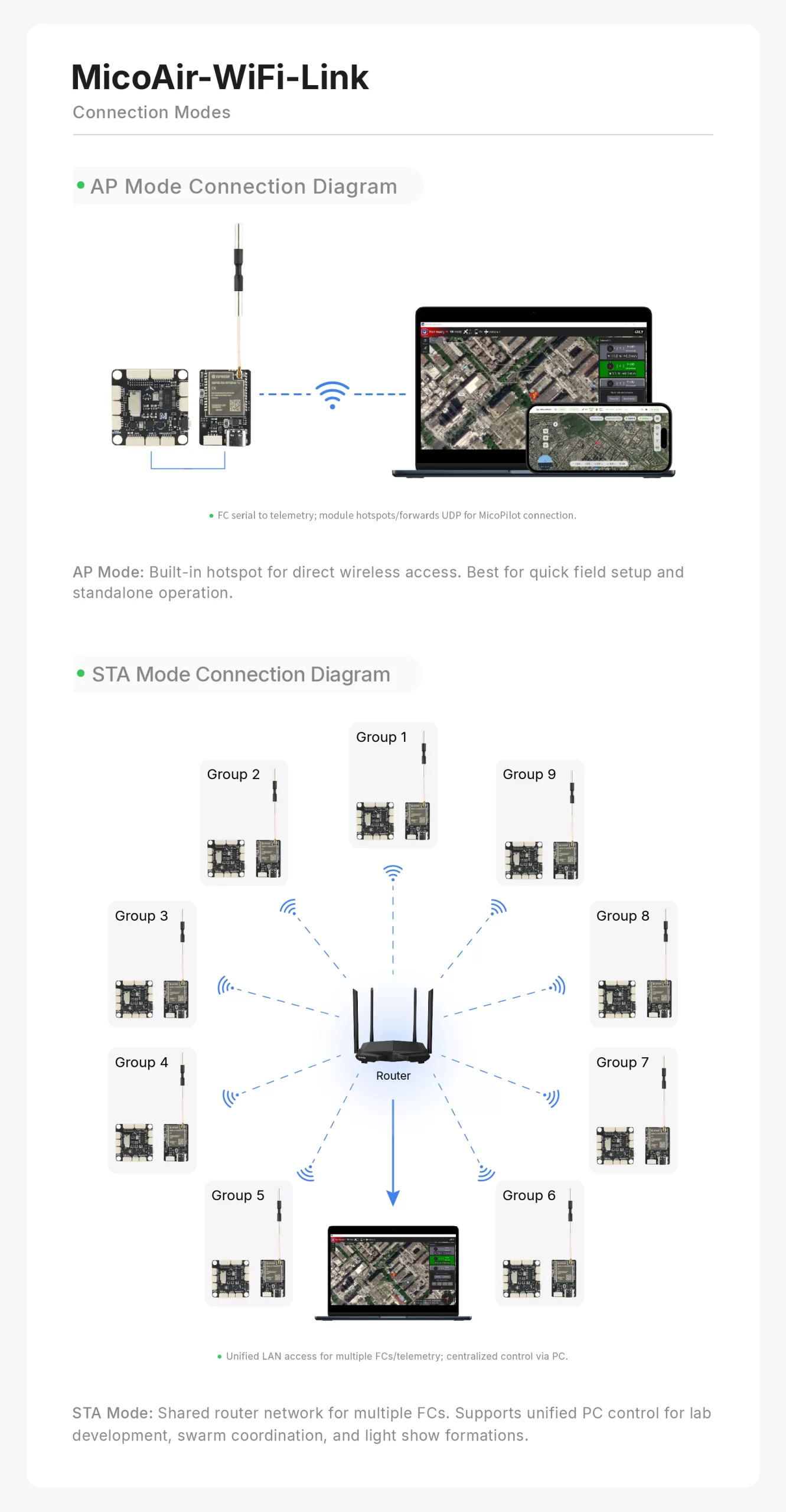
| AP mode (default) | The module creates its own hotspot, and the ground station (computer or phone) connects directly to it. |
| STA mode | The module connects to an existing router, and the ground station communicates with it on the same LAN. |
STA mode supports multi-device networking. For configuration details, see: MicoAir-WiFi-Link Multi-Drone Networking Guide
BLE
- BLE name:
MicoAir_BLE_XXXX - BLE password: No password required
- Note: At present, only the MicoPilot ground control station (GCS) app supports connecting to the flight controller over this BLE link.
- Maximum BLE communication distance: 10 m
- BLE and 2.4 GHz Wi-Fi conflict: BLE and 2.4 GHz Wi-Fi share the same channel and antenna, so only one can be used at a time. The factory default enables 5 GHz Wi-Fi in AP mode together with BLE. Switching to 2.4 GHz Wi-Fi in AP mode automatically disables BLE. In STA mode, connecting to a 2.4 GHz hotspot also disables BLE automatically.
Interfaces
Passthrough Interface
- Cross-connect
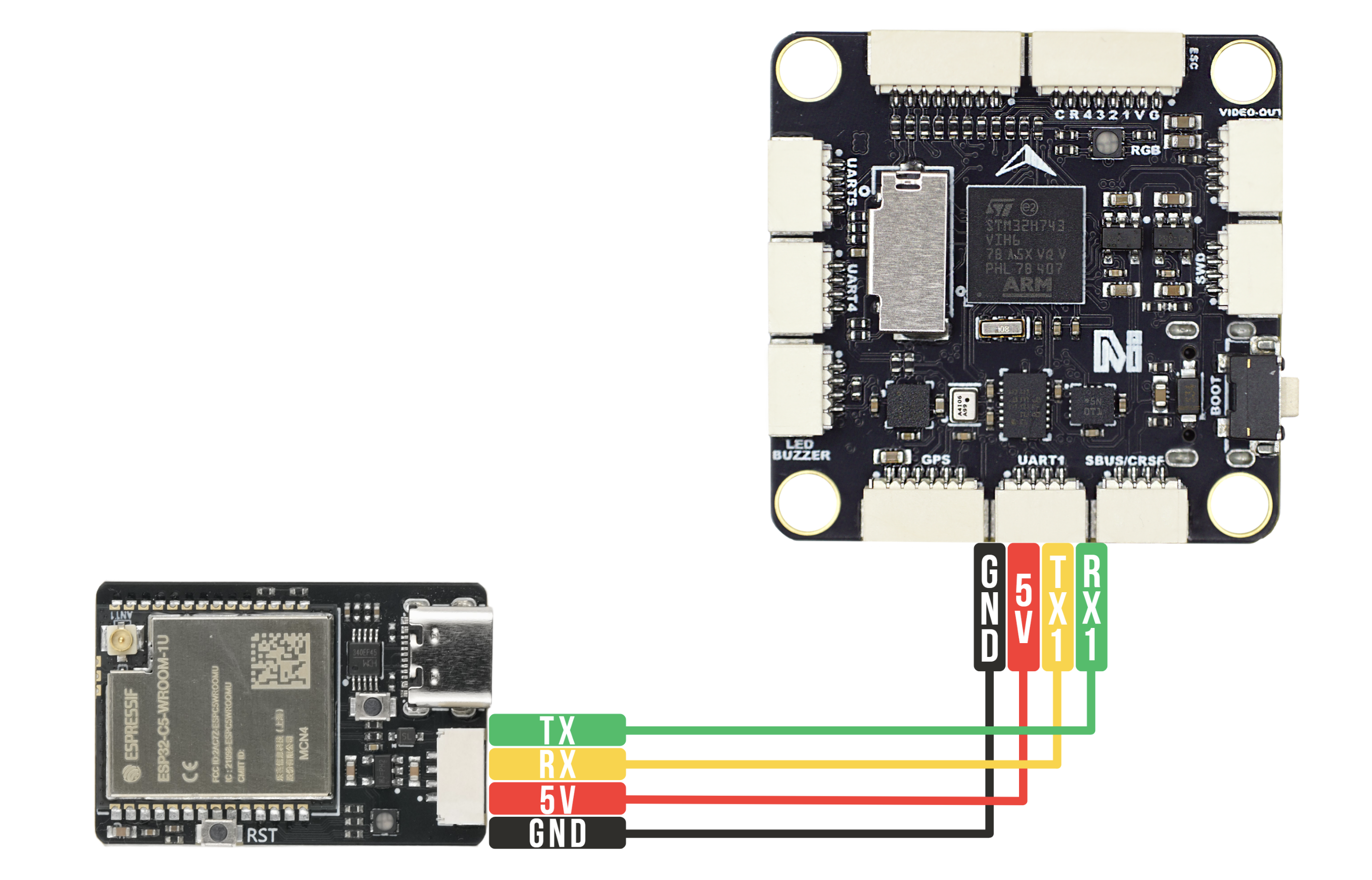
TXandRXbetween the flight controller and telemetry module. - The flight controller and module must share a common ground.
- The flight-controller UART baud rate must match the module setting.
Debug Interface / Driver Download
The module's USB UART is used for:
- Configuring module parameters with
ATcommands - Firmware upgrades
Default parameters:
Baud rate: 115200 / Data bits: 8 / Stop bits: 1 / Parity: None
Wiring Diagram
Web Configuration
In AP mode, open the following address in a browser:
http://192.168.4.1
This page can be used to configure Wi-Fi parameters.
Note that switching to STA mode is supported only through AT-command configuration.
AT Command Configuration
The module supports parameter queries and changes through AT commands sent over USB UART.
Append carriage return and line feed (
\r\n) to every command. When using a UART terminal on a computer, enableSend new lineorAppend CRLF.
Command List
| Command | Description |
|---|---|
AT | Test communication; returns OK |
AT+ALL? | Query all configuration information |
AT+STATUS? | Query the current network and parameter status |
AT+MODE? / AT+MODE=<0/1> | Query / set the operating mode (0: AP mode, 1: STA mode) |
AT+BLE? / AT+BLE=<0/1> | Query / set BLE UART passthrough (0: disabled, 1: enabled) |
AT+CHAN? / AT+CHAN=<1~14> | Query / set the Wi-Fi channel (effective only in AP mode) |
AT+APSSID? / AT+APSSID=<ssid> | Query / set the SSID broadcast by the module (maximum 32 characters) |
AT+APPWD? / AT+APPWD=<pwd> | Query / set the AP password (8–63 characters) |
AT+SSID? / AT+SSID=<ssid> | Query / set the router SSID used in STA mode |
AT+PWD? / AT+PWD=<pwd> | Query / set the router password used in STA mode |
AT+BAUD? / AT+BAUD=<baud> | Query / set the passthrough UART baud rate used to communicate with the flight controller |
AT+PORT? / AT+PORT=<port> | Query / set the UDP communication port (default: 14550) |
AT+MIP? / AT+MIP=<ip> | Query / set the module's local IP address (used in STA mode) |
AT+TIP? / AT+TIP=<ip> | Query / set the target device IP, usually the computer running the ground station (used in STA mode) |
AT+GW? / AT+GW=<ip> | Query / set the gateway address (used with a static IP in STA mode) |
AT+VER? | Query the firmware version |
AT+RST | Restart the module (a restart is required after changing parameters) |
AT+RESET | Restore factory defaults |
AT Command Examples
The following examples cover several common configurations. The module normally returns OK after executing a command successfully.
Example 1: Query the module's current status and parameters
Use this command to confirm the current parameter and network configuration:
Send: AT+STATUS?
Example response:
Mode: AP
AP_SSID: MicoAir_WiFi_Link_ABCD
AP_PWD: 12345678
IP: 192.168.4.1
Baud: 115200
UDP_Port: 14550
Target_IP: 255.255.255.255
OK
Example 2: Change the passthrough UART baud rate
To use a higher baud rate between the flight controller and module, for example 460800:
Send: AT+BAUD=460800
Response: OK

Send: AT+RST
Response: OK
After the module restarts, the passthrough UART uses the new baud rate. Keep the USB debug UART at
115200for AT-command communication, and configure the connected flight-controller UART to the same passthrough baud rate.
Example 3: Switch to STA mode and connect to a router
To extend the communication distance or connect several devices to one LAN, configure the module as a client in STA mode and connect it to an existing wireless router. The following example uses router SSID MyRouter and password password123.
1. Set the router SSID
Send: AT+SSID=MyRouter
Response: OK

2. Set the router password
Send: AT+PWD=password123
Response: OK

3. Set a static IP for the module (each module must use a unique IP that does not conflict with any other device on the LAN)
Send: AT+MIP=192.168.1.101
Response: OK

4. Set the target computer IP
Send: AT+TIP=192.168.1.200
Response: OK

5. Set the operating mode to STA mode (mode number 1)
Send: AT+MODE=1
The module restarts automatically to apply the change
Example 4: Change the default AP password
In the factory-default AP mode, change the AP password to prevent unintended connections. The password must contain at least eight characters.
Send: AT+APPWD=my_new_pwd
Response: OK

Send: AT+RST
Response: OK
(After the module restarts, clients connecting to the module's hotspot must use the new password.)
Ground Station Connection
Before connecting a ground control station, confirm that the telemetry module is wired correctly to the flight-controller UART and that the flight-controller UART uses the MicoAir-WiFi-Link default passthrough baud rate of
115200.
MicoAir-WiFi-Link Multi-Drone Networking Guide
MicoPilot Connection
-
BLE connection: First enable Bluetooth on the phone. Open the MicoPilot GCS app, tap
Connectin the upper-right corner, and selectBluetooth. The Bluetooth connection window opens and lists detected devices automatically. After a few seconds, the MicoAir-WiFi-Link device name (MicoAir_BLE_XXXX) will normally appear in the first row. Tap it to connect, as shown below.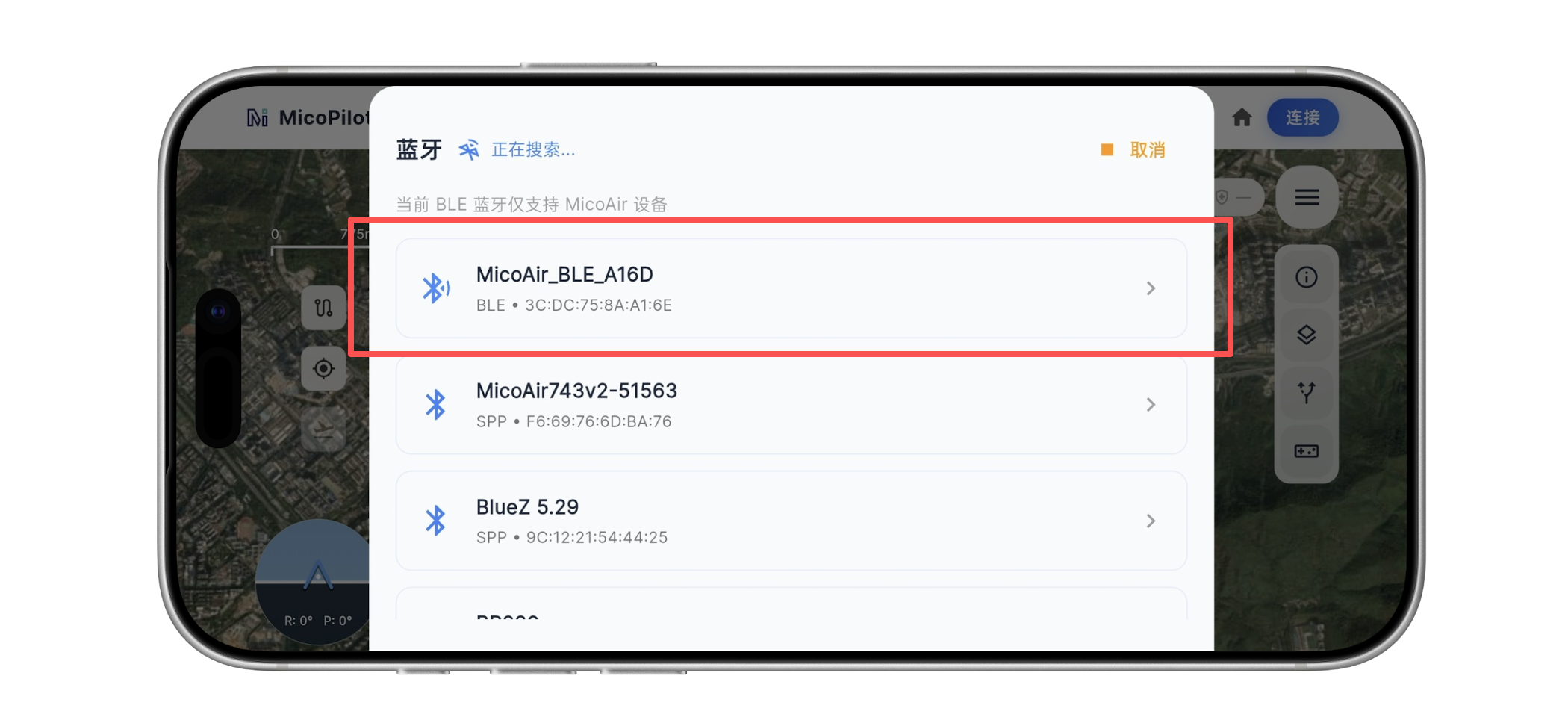
-
Wi-Fi/UDP connection: First connect the phone to the telemetry module's Wi-Fi hotspot, normally named
MicoAir_WiFi_Link_XXXX. Open the MicoPilot GCS app, tapConnectin the upper-right corner, and selectWiFi / UDP. In the UDP connection window, selectUDPCI, leave the gateway IP and port at their defaults of192.168.4.1and14550, and tapConnect.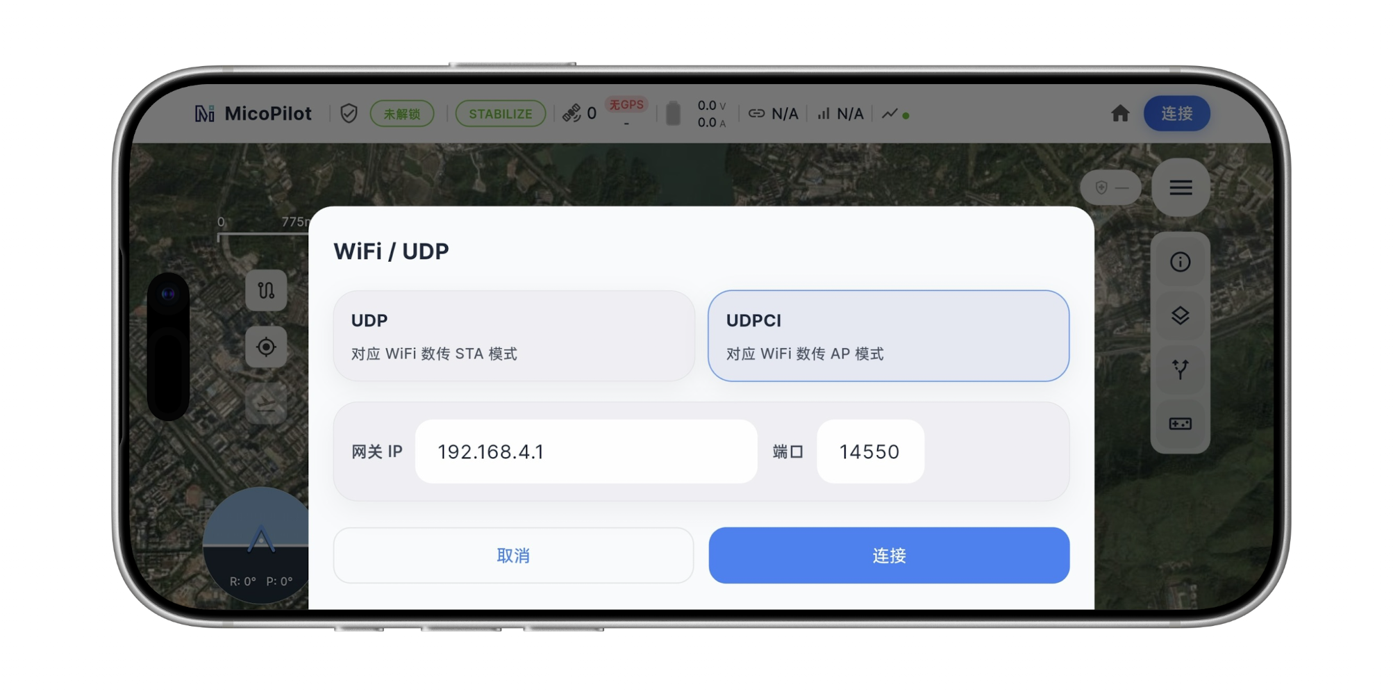
Mission Planner Connection (AP Mode)
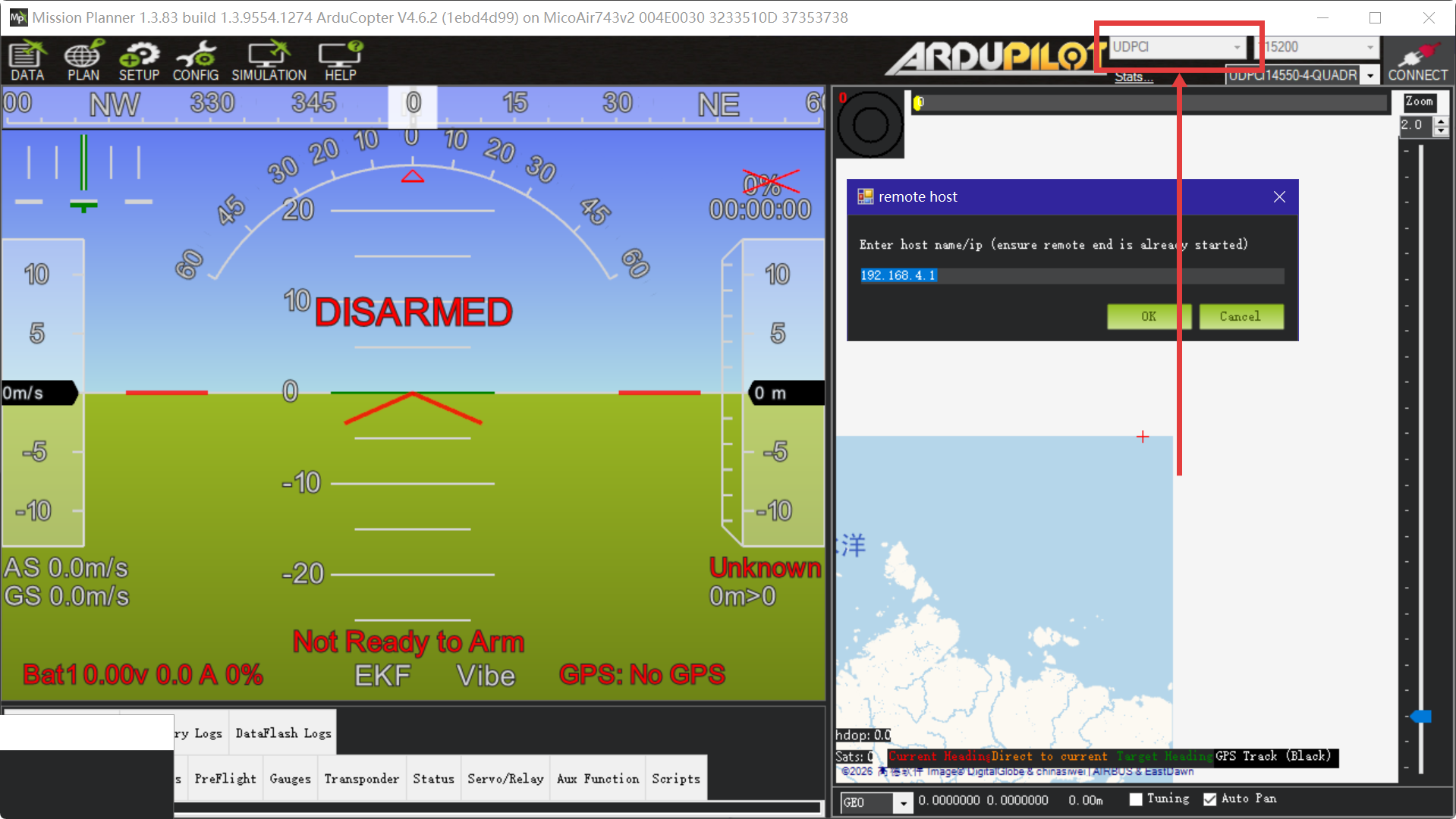
Select UDPCl in the upper-right corner of Mission Planner and click CONNECT. In the dialog, enter the telemetry-module gateway IP address 192.168.4.1 and port 14550. Mission Planner will begin connecting to the flight controller automatically. If it cannot connect or retrieve parameters after an extended period, verify that Wi-Fi is connected, the flight-controller UART baud rate is set to 115200, and RX and TX are cross-connected correctly.
QGroundControl Connection
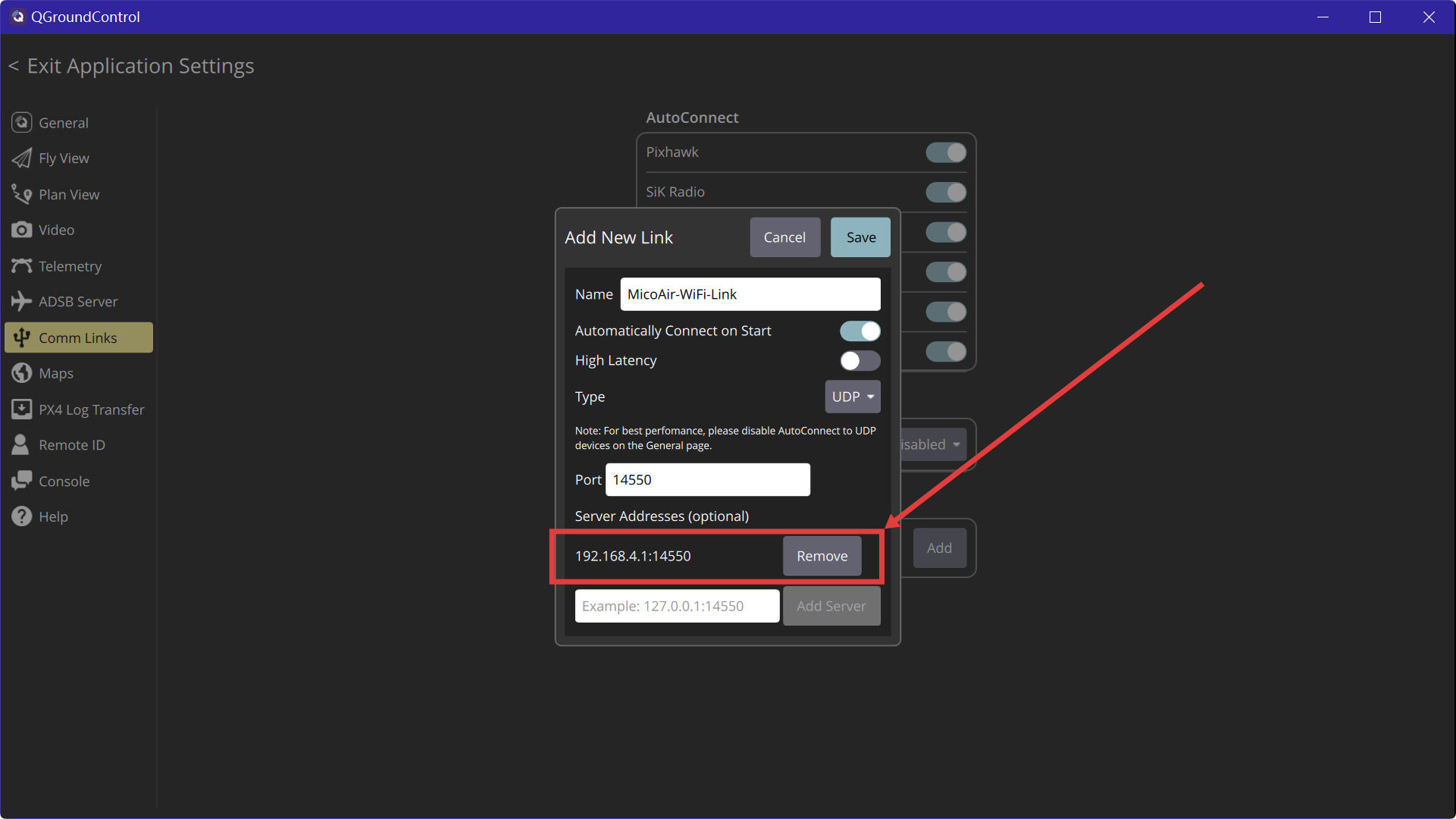
Open QGroundControl and go to Application Settings → Comm Links. Click Add to create a link, set Type to UDP, set Port to 14550, add 192.168.4.1:14550 under Server Addresses, enable Automatically Connect on Start, and click Save. Keep the global AutoConnect → UDP option disabled when using this manually configured link. Select the newly created link and click Connect. QGroundControl will use the saved configuration automatically the next time it starts. If the connection still fails, first add QGroundControl to the Windows Firewall allowlist. Temporarily disable the firewall only for diagnosis, and re-enable it immediately after the test.