
Docs directory
Table of contents
MicoAir RTK Series User Manual
Product Overview
The MicoAir RTK series is a high-precision GNSS positioning solution developed by MicoAir for UAVs and other robotic platforms. It combines a base station with multiple rover-module options to provide centimeter-level positioning:
-
Centimeter-level positioning: The base station and rover module work together to achieve positioning accuracy down to 1 cm under suitable conditions.
-
Multi-constellation, multi-frequency reception: Covers the L1, L2, and L5 bands and supports GPS, BeiDou, GLONASS, Galileo, and QZSS.
-
RTCM compatibility: The base station outputs standard RTCM correction data compatible with most RTK modules.
-
Open-source compatibility: Supports major open-source autopilot firmware, including ArduPilot and PX4.
Models and Key Features
Base station
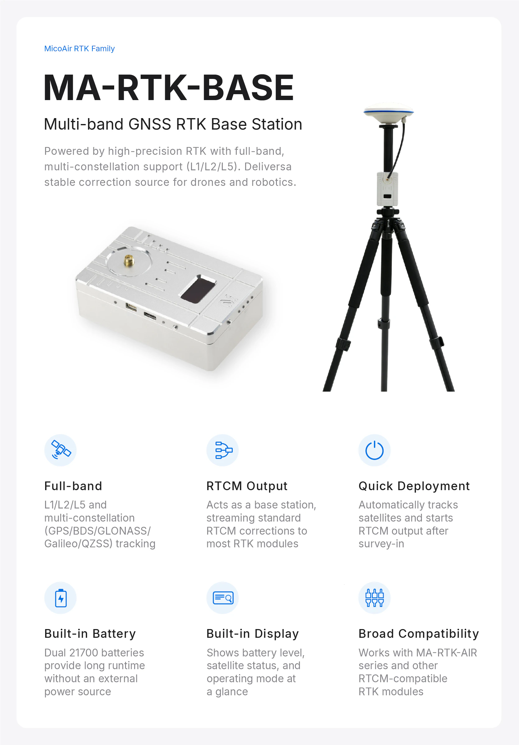
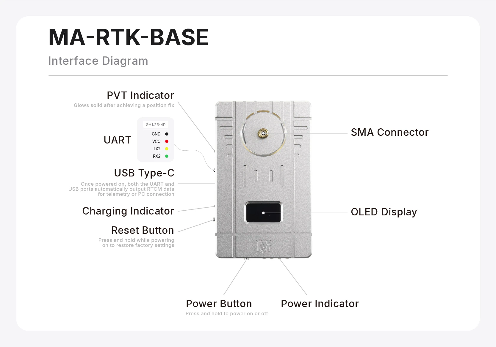
- MA-RTK-BASE: Quick tripod setup with a built-in 21700 battery. It supports multi-constellation, multi-frequency reception and outputs standard RTCM correction data for MicoAir RTK rover modules and compatible third-party RTK modules.
Rover modules
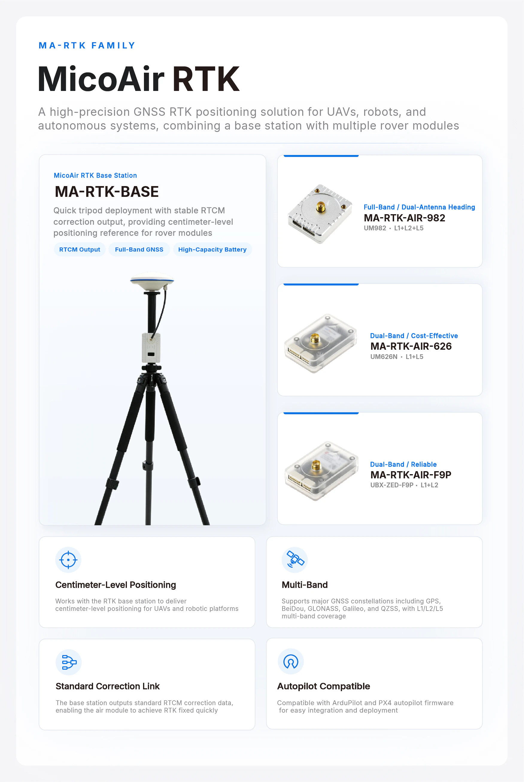
- MA-RTK-AIR-982: Supports multi-constellation L1+L2+L5 reception and dual-antenna heading. It is intended for industrial UAVs operating in magnetically challenging environments and unmanned ground vehicles operating in complex terrain.
- MA-RTK-AIR-F9P: Uses the u-blox ZED-F9P L1+L2 dual-frequency solution and supports both ArduPilot and PX4.
- MA-RTK-AIR-626: A cost-effective UM626N-based L1+L5 dual-frequency solution with low power consumption, suitable for cost-sensitive applications and large-scale deployments such as drone light-show fleets.
Purchase
Product Features
MA-RTK-BASE
-
Base station port settings: Both USB Type-C (UART1) and GH1.25-4P (UART2) use a default baud rate of 115200, with RTCM output at 1 Hz. These settings can be changed using Allystar UPrecise software, but should be left unchanged unless you are familiar with GNSS receiver configuration.
-
USB-to-serial driver (CH340): Download CH340 Driver
-
Typical operating time: approximately 12 hours under load (including an active RTK antenna and a telemetry radio averaging 1 W)
-
Built-in battery: 2 standard 21700 lithium cells, 5000 mAh each
-
Maximum charging power: 10 W (5 V, 2 A)
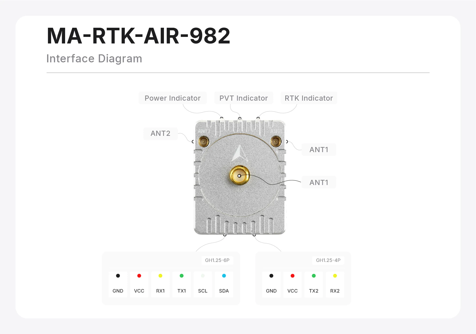
MA-RTK-AIR-982
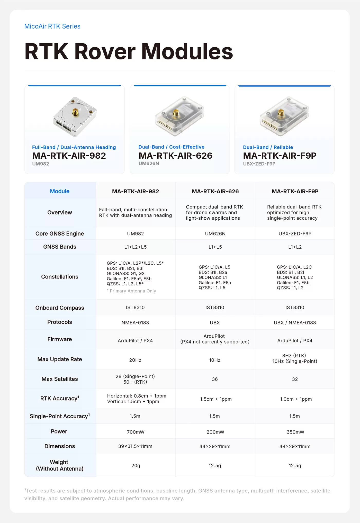
- GNSS receiver: UM982
- GNSS frequency bands: L1 + L2 + L5
- Supported satellite systems: GPS: L1C/A, L2P*/L2C, L5*; BDS: B1I, B2I, B3I; GLONASS: G1, G2; Galileo: E1, E5a*, E5b; QZSS: L1, L2, L5* (an asterisk indicates that only the primary ANT1 antenna supports that frequency)
- Onboard magnetometer: IST8310
- Output protocol: NMEA 0183 (no data output in the factory configuration; the flight controller configures it automatically)
- Default port baud rate: 115200 (normally configured automatically by the flight controller to 230400)
- Supported autopilot firmware: ArduPilot / PX4
- Maximum navigation update rate: 20 Hz
- Maximum number of satellites: 28 (standalone) / 50+ (RTK)
- RTK positioning accuracy1: Horizontal 0.8 cm + 1 ppm; vertical 1.5 cm + 1 ppm
- Standalone positioning accuracy1: 1.5 m
- VCC supply voltage: 4–5 V
- Module power consumption: 700 mW
- Serial logic level: 3.3 V LVTTL
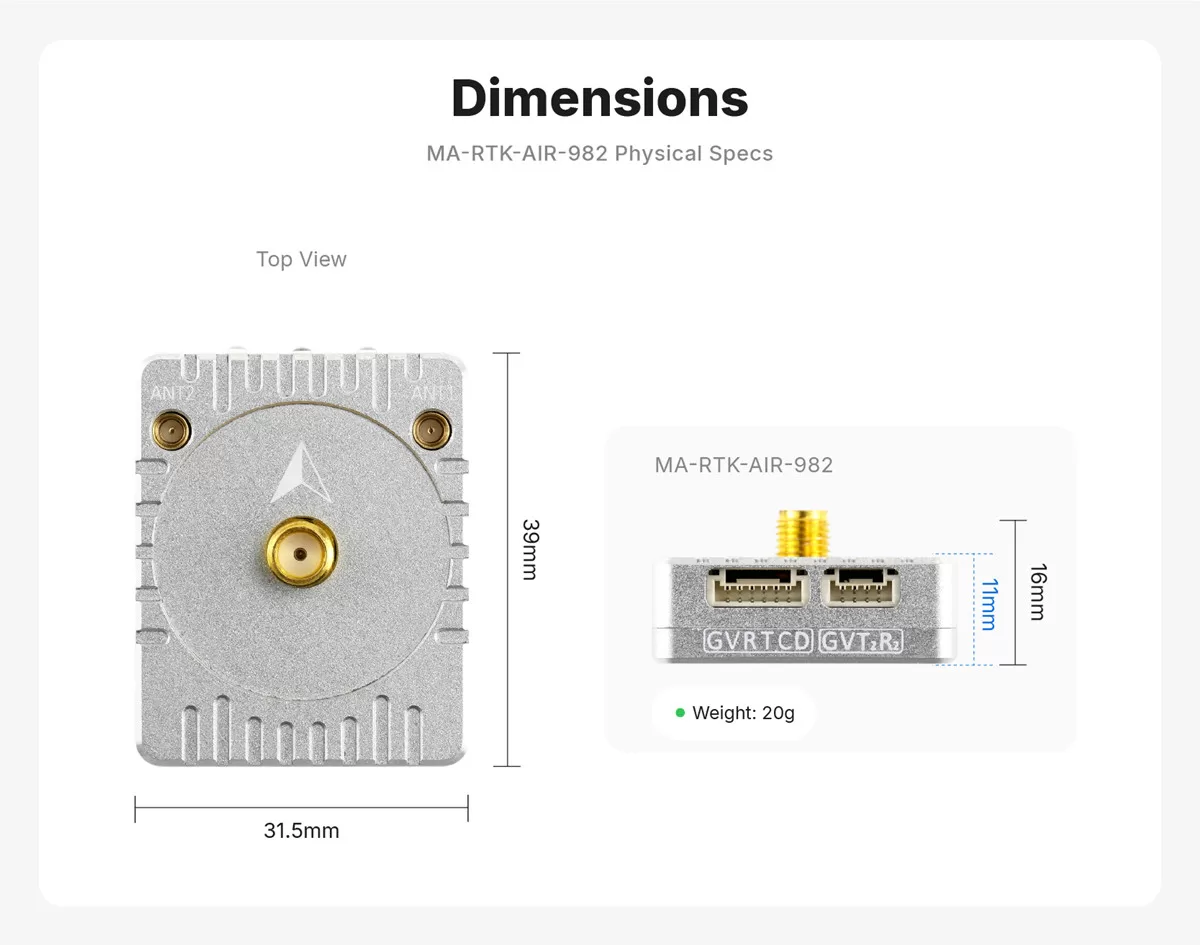
- Dimensions: 39 × 21.5 × 16 mm
- Weight: 20 g (excluding antennas)
- Antenna connectors: MMCX × 2, SMA × 1
- Data connectors: GH1.25-6P × 1, GH1.25-4P × 1
Do not connect antennas to both ANT1 connectors at the same time. Use only one ANT1 connector.
1 Test results may vary with atmospheric conditions, baseline length, GNSS antenna performance, multipath, the number of visible satellites, and satellite geometry.
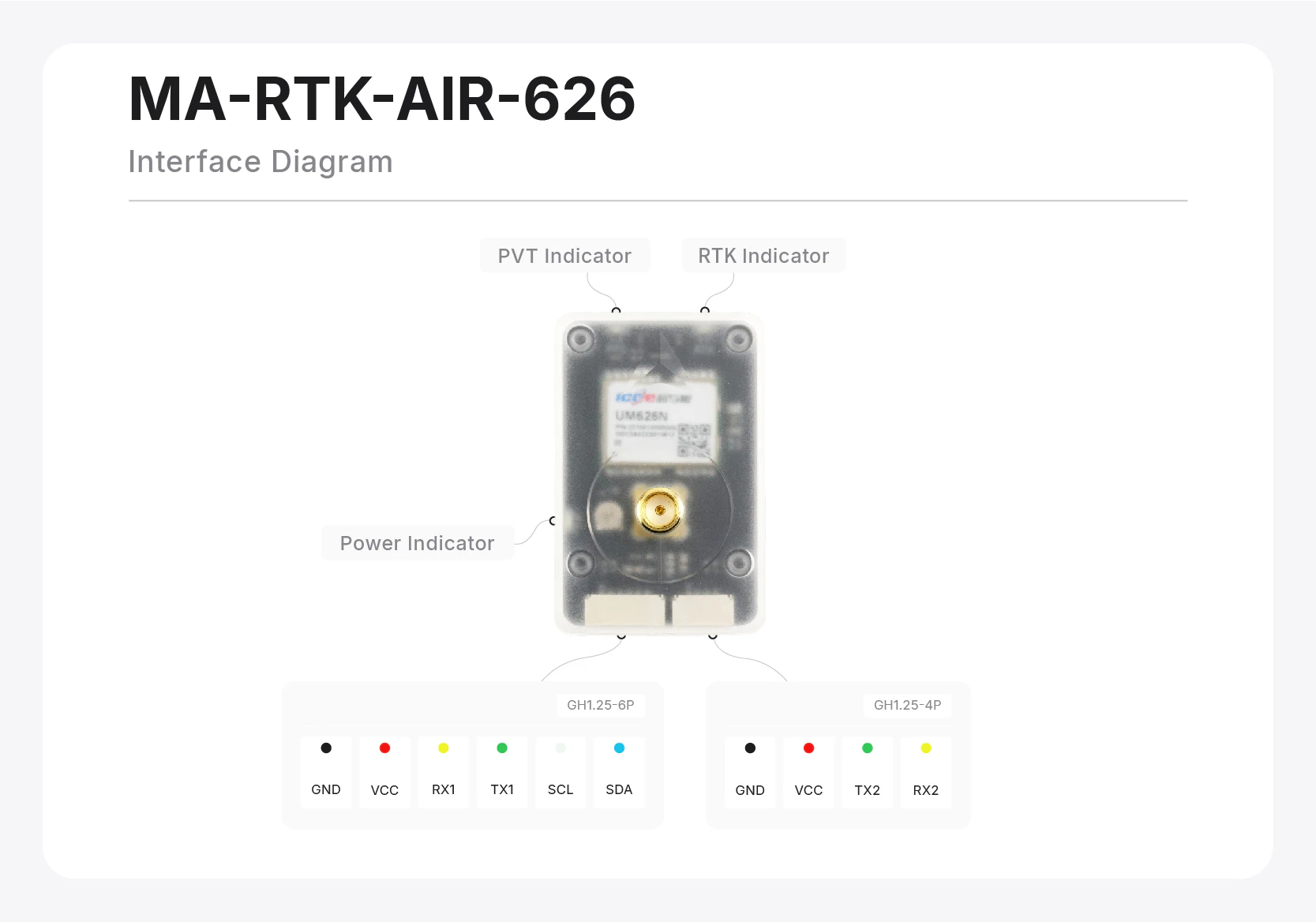
MA-RTK-AIR-626
- GNSS receiver: UM626N
- GNSS frequency bands: L1 + L5
- Supported satellite systems: GPS: L1C/A, L5; BDS: B1I, B2a; GLONASS: G1; Galileo: E1, E5a; QZSS: L1, L5
- Onboard magnetometer: IST8310
- Output protocol: UBX (u-blox-compatible protocol)
- Port baud rate: 115200 (not configurable)
- Supported autopilot firmware: ArduPilot (PX4 is not currently supported)
- Maximum navigation update rate: 10 Hz
- Maximum number of satellites: 36
- RTK positioning accuracy1: 1.5 cm + 1 ppm
- Standalone positioning accuracy1: 1.5 m
- VCC supply voltage: 4–5 V
- Module power consumption: 200 mW
- Serial logic level: 3.3 V LVTTL
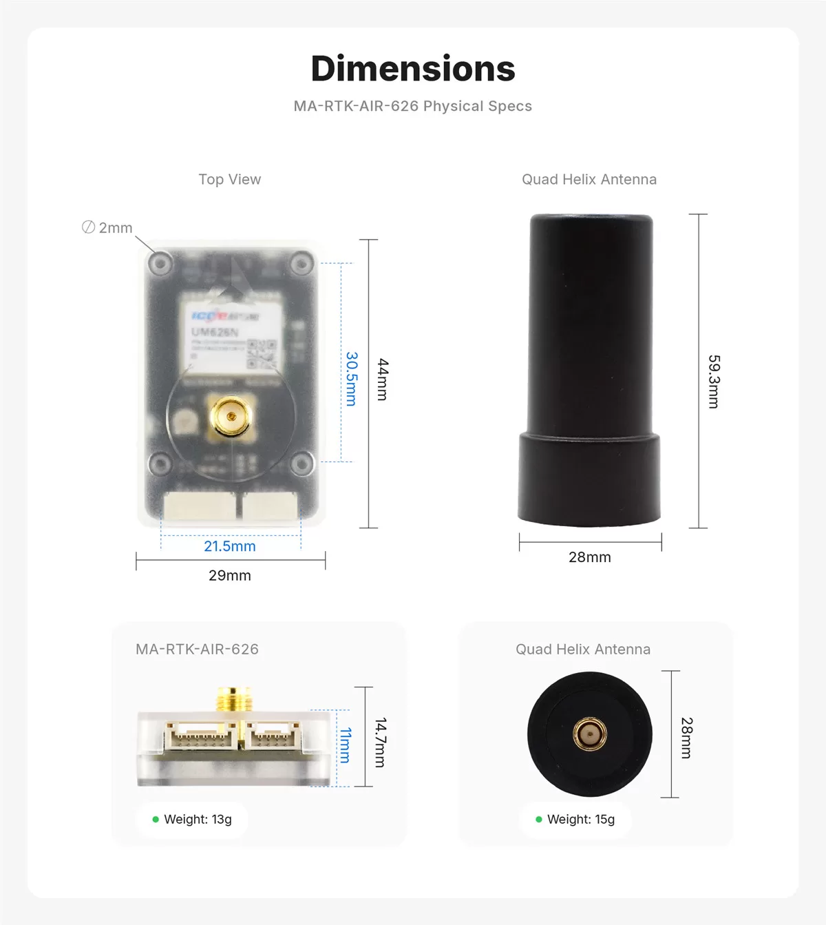
- Dimensions: 44 × 29 × 14.7 mm
- Weight: 13 g (excluding antenna)
- Antenna connector: SMA
- Data connectors: GH1.25-6P × 1, GH1.25-4P × 1
1 Test results may vary with atmospheric conditions, GNSS antenna performance, multipath, the number of visible satellites, and satellite geometry.
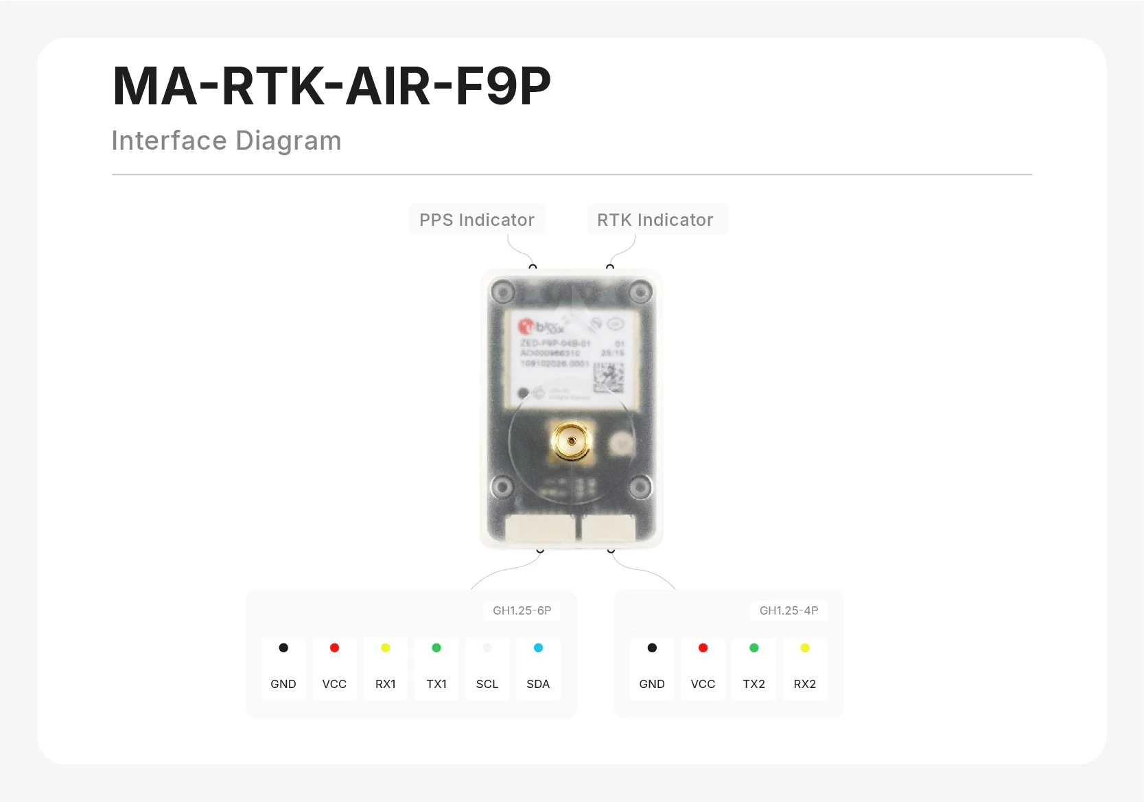
MA-RTK-AIR-F9P
- GNSS receiver: u-blox ZED-F9P
- GNSS frequency bands: L1 + L2
- Supported satellite systems: GPS: L1C/A, L2C; BDS: B1I, B2I; GLONASS: G1, G2; Galileo: E1, E5b; QZSS: L1, L2
- Onboard magnetometer: IST8310
- Output protocols: UBX / NMEA 0183
- Default port baud rate: 38400 (normally configured automatically by the flight controller to 230400)
- Supported autopilot firmware: ArduPilot / PX4
- Maximum navigation update rate: 8 Hz (RTK), 10 Hz (standalone)
- Maximum number of satellites: 32
- RTK positioning accuracy1: 1.0 cm + 1 ppm
- Standalone positioning accuracy1: 1.5 m
- VCC supply voltage: 4–5 V
- Module power consumption: 350 mW
- Serial logic level: 3.3 V LVTTL
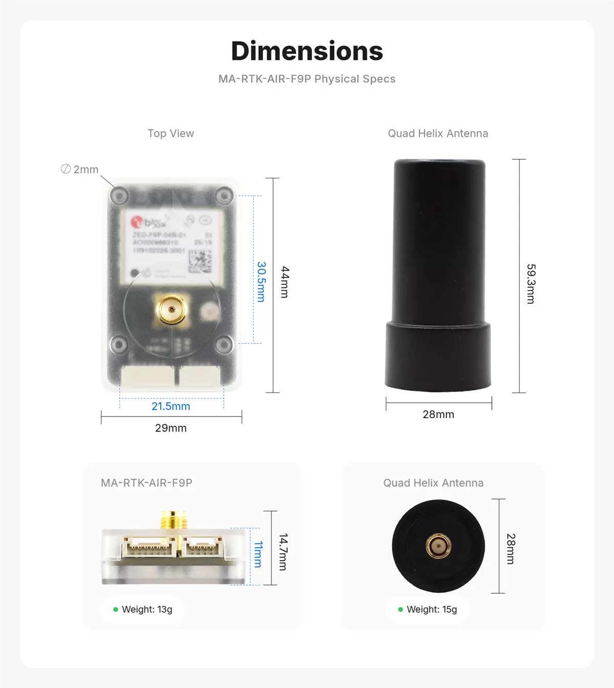
- Dimensions: 44 × 29 × 14.7 mm
- Weight: 13 g (excluding antenna)
- Antenna connector: SMA
- Data connectors: GH1.25-6P × 1, GH1.25-4P × 1
1 Test results may vary with atmospheric conditions, GNSS antenna performance, multipath, the number of visible satellites, and satellite geometry.
RTK Operating Modes
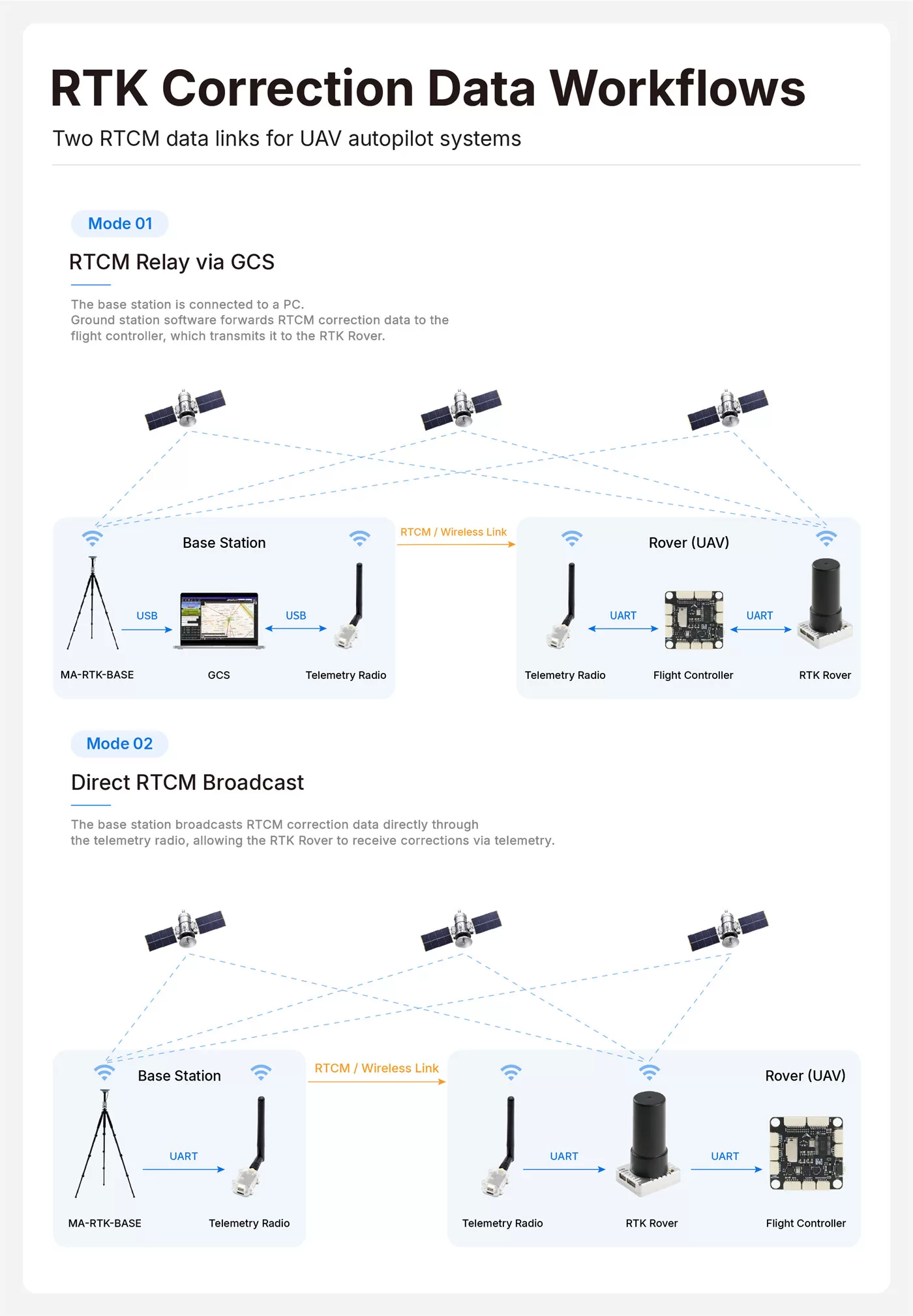
An RTK rover module must receive RTCM correction data from a base station to achieve centimeter-level positioning. Two common RTCM link modes are available:
-
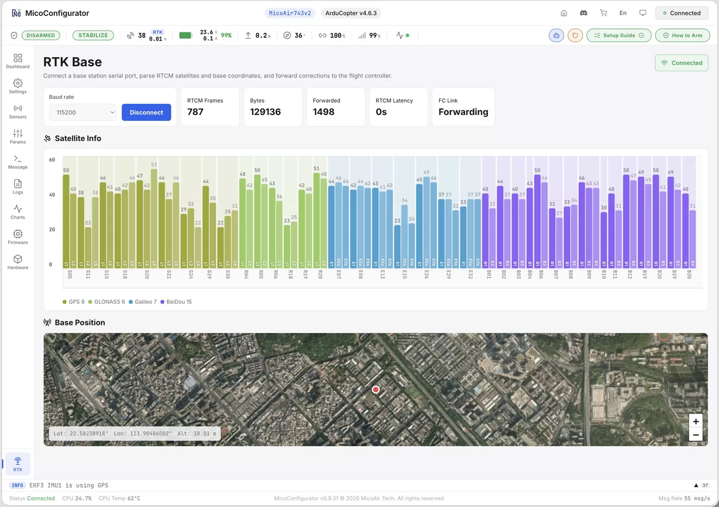
Ground control station (GCS) forwarding: The base station connects to a computer through USB. GCS software receives the RTCM data from the base station and forwards it to the connected flight controller, usually over a wireless telemetry link. Mission Planner, QGroundControl, and MicoConfigurator support RTCM forwarding.
-
Base station telemetry broadcast: The base station broadcasts RTCM data over a telemetry radio. The RTK rover module uses a separate telemetry radio to receive the RTCM data and apply the corrections.
The following example shows MicoConfigurator connected to the base station and automatically forwarding RTCM data to the flight controller:
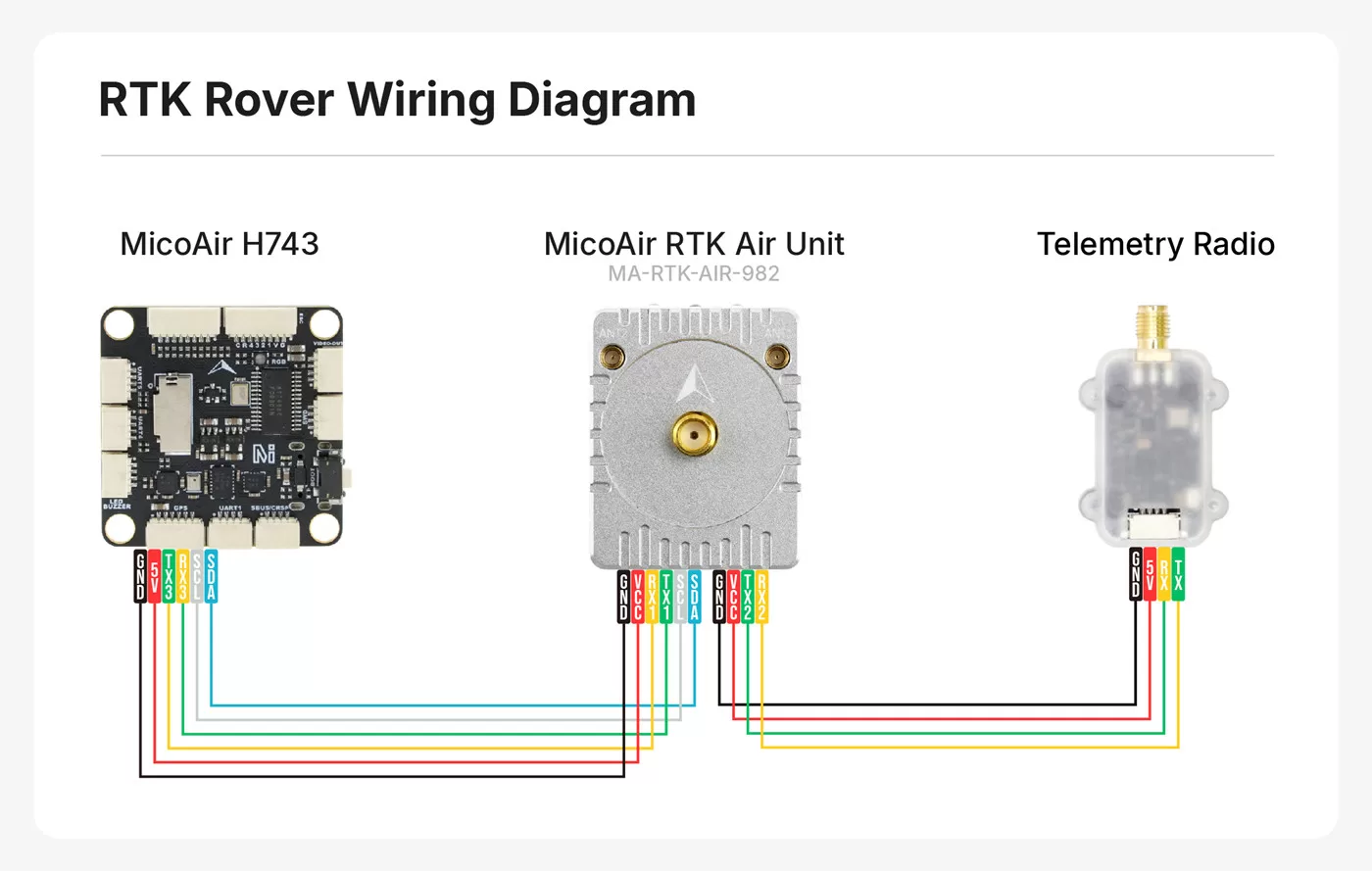
Flight Controller Wiring
The rover module's 4-pin connector is normally used for an optional telemetry radio that receives RTCM correction data. No telemetry radio is required when GCS forwarding is used.
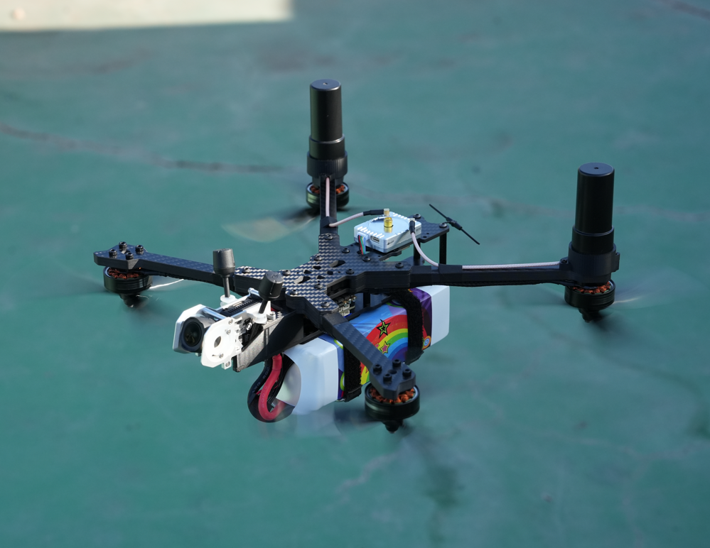
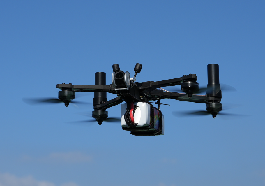
MA-RTK-AIR-982 dual-antenna installation example (for reference only)
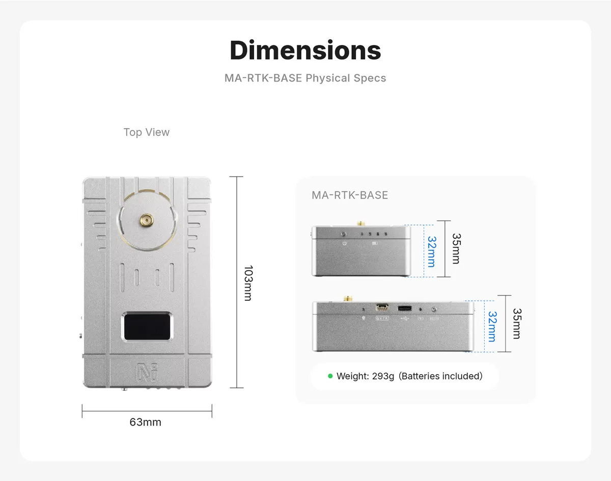
Dimensions
Flight Controller Configuration
MA-RTK-AIR-F9P
As with conventional u-blox GPS modules, ArduPilot and PX4 can automatically detect and configure the F9P, so the flight-controller defaults can be retained. If the GPS is not detected, first check the hardware connection, including the selected port and pin order.
MA-RTK-AIR-626
The MA-RTK-AIR-626 currently supports only ArduPilot, including Skybrush. It cannot yet be used with PX4 firmware.
In ArduPilot, disable automatic GPS configuration by setting GPS_AUTO_CONFIG = 0; leave the other parameters at their default values. The MA-RTK-AIR-626 should then be detected automatically.
MA-RTK-AIR-982
ArduPilot Configuration
Without dual antennas:
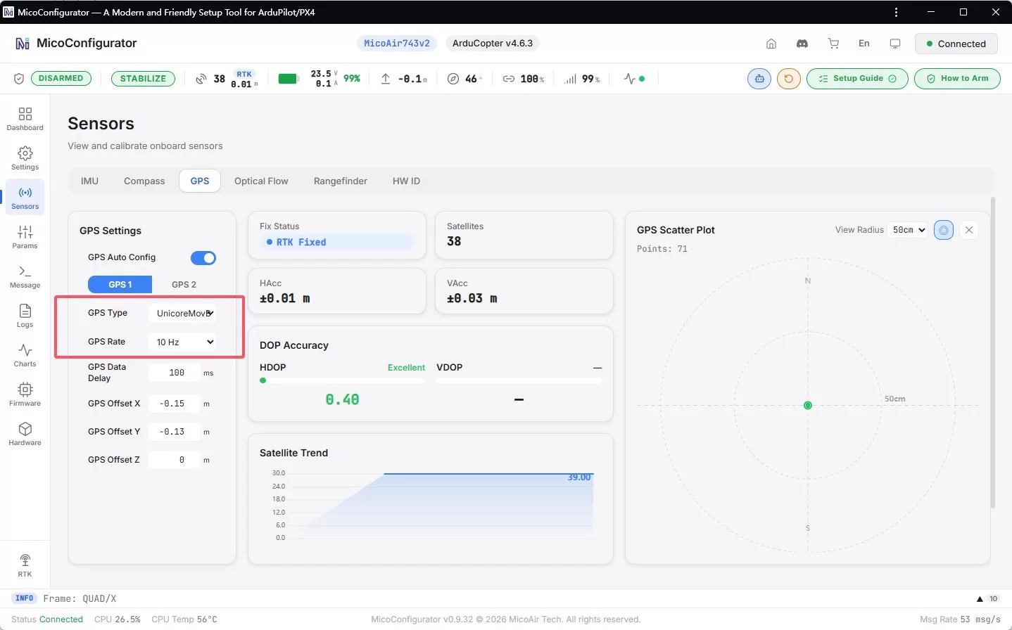
GPS1_TYPE = 24(UnicoreNMEA)GPS1_RATE_MS = 100(10 Hz)
Alternatively, configure the module directly on the GPS page in MicoConfigurator:
With dual antennas:
The baseline length—the horizontal distance between the two antennas—must be at least 20 cm to achieve good heading accuracy.
GPS1_TYPE = 25(UnicoreMovingBaselineNMEA)GPS1_RATE_MS = 100(10 Hz)GPS_MB1_TYPE = 1: Selects the type used by GPS 1 in Moving Base mode for a dual-antenna RTK/heading configuration. After changing this parameter, refresh the parameter list or reconnect the flight controller before theGPS_MB1_OFS_*subparameters appear.
The antenna-offset parameters are essential for calculating real-time heading from dual-antenna RTK. Measure and configure them carefully.
GPS_MB1_OFS_X: X-axis offset of the primary antenna relative to the secondary antenna, in meters. The value is positive when the primary antenna is in front of the secondary antenna and negative when it is behind.GPS_MB1_OFS_Y: Y-axis offset of the primary antenna relative to the secondary antenna, in meters. The value is positive when the primary antenna is to the right of the secondary antenna and negative when it is to the left.GPS_MB1_OFS_Z: Z-axis offset of the primary antenna relative to the secondary antenna, in meters. The value is positive when the primary antenna is below the secondary antenna and negative when it is above.
For better positioning while the vehicle rotates in place, also configure the primary-antenna position offsets GPS_POS1_X, GPS_POS1_Y, and GPS_POS1_Z.
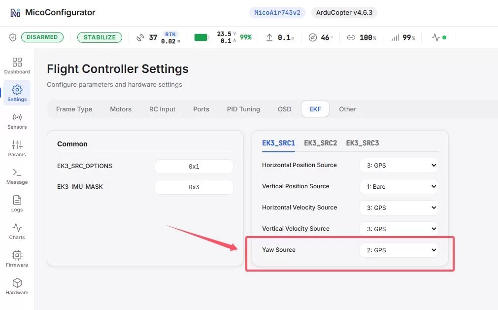
Set EK3_SRC1_YAW to 2 (GPS) so that the flight controller's heading estimator uses the dual-antenna heading data. If a compass is installed and should remain available as a fallback, select 3 (GPS with Compass Fallback) instead.
PX4 Configuration
Set GPS_1_PROTOCOL = 6 (NMEA (generic)), and then reboot the flight controller so that PX4 can detect the GNSS receiver.
Set EKF2_GPS_CTRL = 15 to enable dual-antenna heading.
Set GPS_YAW_OFFSET according to the antenna layout. If the primary antenna is in front of the secondary antenna and both antennas are aligned with the vehicle's forward axis, set it to 0°. Angles increase clockwise. If the primary antenna is on the right side of the vehicle and the secondary antenna is on the left, set it to 90°.
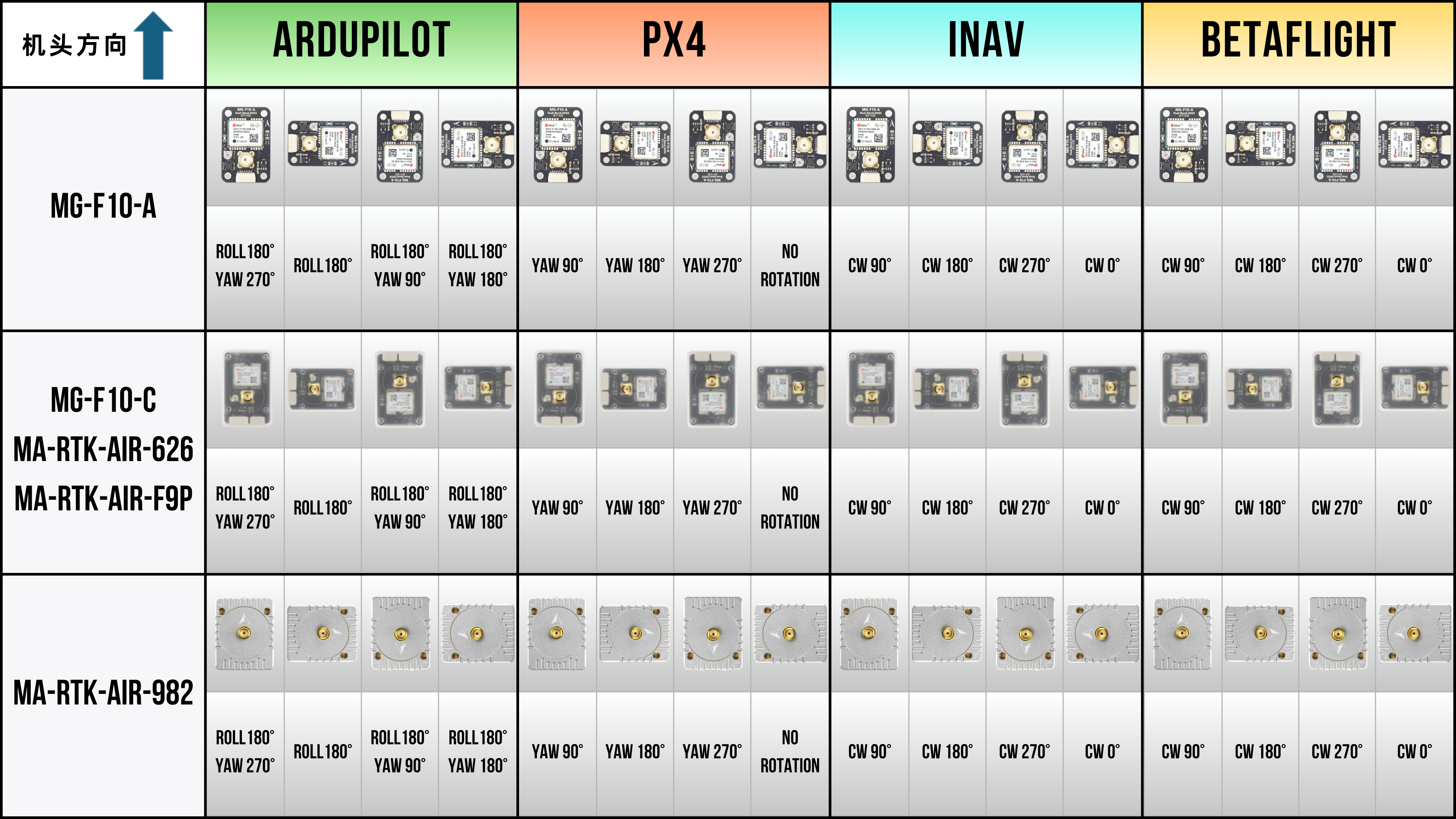
Flight Controller Compass Orientation Parameters