

Docs directory
Table of contents
MicoAir743-Lite User Manual
Product Overview
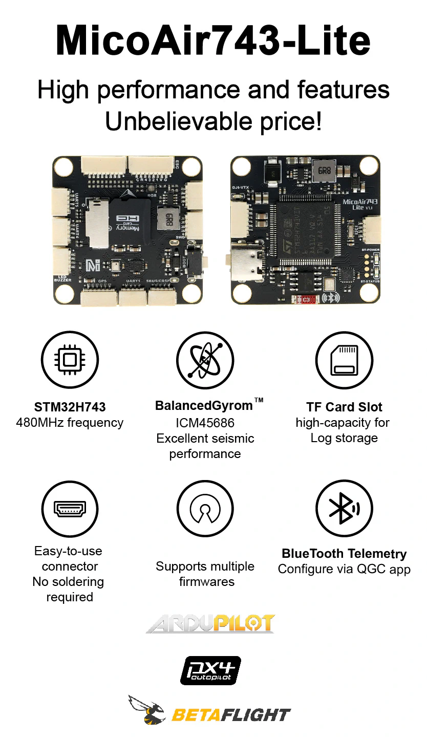
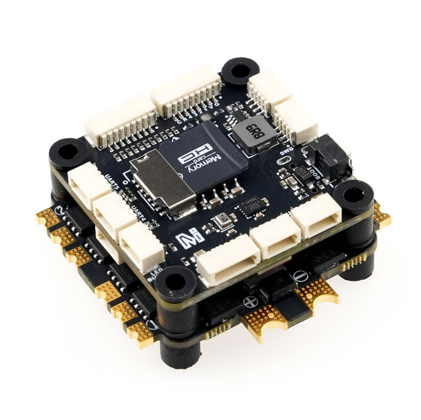
The MicoAir743-Lite is a lightweight, high-performance H743 flight controller from MicoAir. It uses a 480 MHz STM32H743VIT6, an ICM45686 IMU with low temperature drift and high vibration tolerance, an SPA06 barometer, a microSD card slot for flight logs, and onboard Bluetooth telemetry connected to UART8.
The flight controller provides 8 UARTs, 15 PWM outputs, 1 I²C bus, 5 V / 2 A and 9 V / 2 A BEC outputs, and DisplayPort support for DJI O3/O4 digital video transmitters. It supports ArduPilot, PX4, and Betaflight firmware. INAV does not currently support this board because support for its ICM45686 IMU has not yet been implemented.
Key Features
STM32H743VIT6, 480 MHz, 2 MB FlashICM45686IMU with BalancedGyro™ technologySPA06barometer- 8 UARTs, 15 PWM outputs, and 1 I²C bus
- PWM1–PWM8 support DShot and bidirectional DShot; availability depends on firmware support
- microSD card slot for flight logs
- Onboard Bluetooth telemetry connected to UART8 with a default baud rate of
115200 - DJI O3/O4/O4 Pro-compatible connector
- 5 V / 2 A and 9 V / 2 A BEC outputs
- 2–6S battery input, 6–27 V
- No onboard magnetometer or analog OSD
Where to Buy
Hardware Specifications
Processor and Sensors
| Item | Specification |
|---|---|
| Main MCU | STM32H743VIT6, 480 MHz, 2 MB Flash |
| IMU | ICM45686 |
| Barometer | SPA06 |
| Onboard magnetometer | None; an external magnetometer can be connected over I²C |
| Analog OSD | None; digital video transmitters can use DisplayPort |
| Log storage | microSD card slot |
Interfaces and Outputs
| Item | Quantity / Description |
|---|---|
| UART | 8 |
| PWM | 15 outputs; PWM15 shares its pin with the serial LED output |
| I²C | 1 |
| SWD | 1 |
| ADC | Two channels for battery voltage and current sensing |
| USB | USB Type-C |
| Digital video | Compatible with DJI O3/O4/O4 Pro; UART2 DisplayPort by default |
| RC receiver | UART6 is the default RC input |
| Bluetooth | Onboard, connected to UART8; default baud rate: 115200 |
| Other | Buzzer, serial LED, and BOOT button/pad |
Power and Mechanical Specifications
| Item | Specification |
|---|---|
| Battery input | 2–6S, 6–27 V |
| 5 V BEC | 2 A maximum |
| 9 V BEC | 2 A maximum |
| Mounting pattern | 30.5 × 30.5 mm |
| Mounting hole diameter | Φ4 mm |
| Dimensions | 36 × 36 × 8 mm |
| Weight | 10 g |
Dimensions and Installation
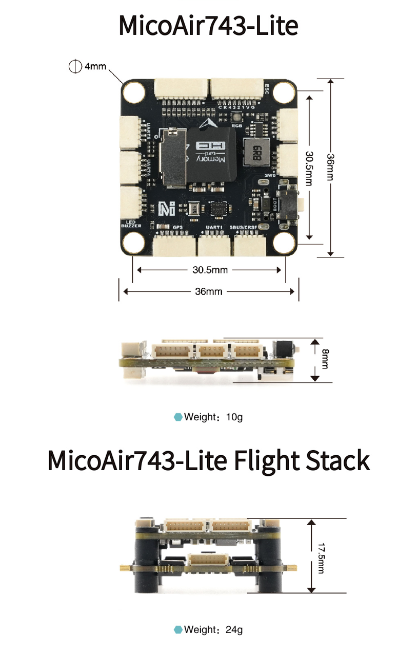
- Secure the flight controller using the 30.5 × 30.5 mm mounting pattern and vibration-damping standoffs.
- Tighten the screws evenly. Do not bend the PCB or allow metal parts to touch board components.
- Keep the flight-direction mark pointed toward the nose. If the board is installed at another orientation, configure the correct rotation in firmware.
- Insert or remove the microSD card only while power is disconnected.
Connectors and Power
Connector Layout
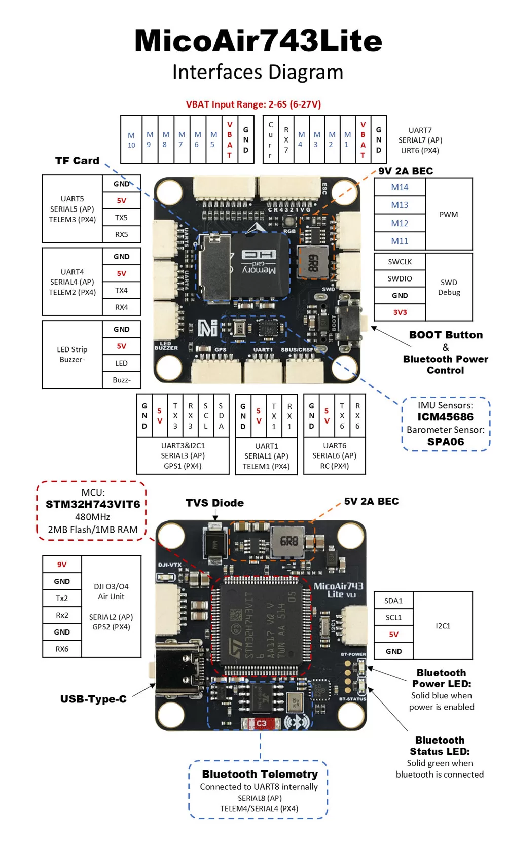
Typical Wiring
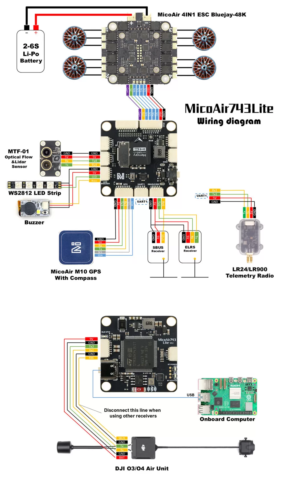
Power Requirements
| Interface | Voltage | Typical use | Notes |
|---|---|---|---|
VBAT | 6–27 V | Main flight controller power | Connect only a 2–6S battery or equivalent supply |
5V | 5 V | RC receiver, GNSS receiver, optical flow sensor, or rangefinder | Verify the peripheral input range |
9V | 9 V | DJI video transmitter, camera | Do not connect peripherals that support only 5 V |
GND | 0 V | Power and signal reference ground |
Pin 1 on the digital video connector is 9 V. Verify the pin order and peripheral input voltage before connecting a DJI O3/O4/O4 Pro.
Serial Port Mapping
ArduPilot Serial Port Mapping
| ArduPilot Port | Physical Interface | Default Function / Features |
|---|---|---|
SERIAL0 | USB | USB virtual serial port |
SERIAL1 | UART1 | MAVLink2 with DMA support |
SERIAL2 | UART2 | DisplayPort with DMA support |
SERIAL3 | UART3 | GNSS receiver with DMA support |
SERIAL4 | UART4 | MAVLink2 with DMA support |
SERIAL5 | UART5 | General-purpose serial port with DMA support |
SERIAL6 | UART6 | RC input with DMA support |
SERIAL7 | UART7 | ESC telemetry with DMA support |
SERIAL8 | UART8 | Onboard Bluetooth telemetry with DMA support |
PX4 Serial Port Mapping
| PX4 Device | PX4 Port Name | Physical Interface |
|---|---|---|
ttyACM0 | USB | USB virtual serial port |
ttyS0 | TELEM1 | UART1 |
ttyS1 | GPS2 | UART2 |
ttyS2 | GPS1 | UART3 |
ttyS3 | TELEM2 | UART4 |
ttyS4 | TELEM3 | UART5 |
ttyS5 | RC | UART6 |
ttyS6 | URT6 | UART7 |
ttyS7 | TELEM4 / SERIAL4 | UART8 |
UART8 is used by the onboard Bluetooth module at a default baud rate of
115200. UART2 is shared with the digital video DisplayPort connector.
PWM, ESCs, and Serial LEDs
The MicoAir743-Lite provides up to 15 PWM outputs. PWM1–PWM8 support DShot and bidirectional DShot. PWM15 shares its pin with the serial LED output.
PWM Timer Groups
| Group | Channels | Description |
|---|---|---|
| Group 1 | PWM1, PWM2, PWM3, PWM4 | Protocol and frequency must be compatible within the group |
| Group 2 | PWM5, PWM6, PWM7, PWM8 | Same timer-group constraints apply |
| Group 3 | PWM9, PWM10 | Same timer-group constraints apply |
| Group 4 | PWM11, PWM12, PWM15 | PWM15 is also the serial LED pin |
| Group 5 | PWM13, PWM14 | Same timer-group constraints apply |
When PWM15 is configured for a serial LED, PWM11 and PWM12 share the same timer-group constraints and may be limited to settings compatible with the serial LED output.
Remove all propellers before testing the motors. Start with
DShot300; install the propellers only after verifying motor numbering, direction, and failsafe behavior.
RC Receiver
UART6 is the default RC input, although another unused UART can also be configured for the receiver.
| Protocol | Recommended wiring | Notes |
|---|---|---|
| SBUS / DSM / SRXL | Signal → RX6 | Supply the voltage required by the receiver |
| FPort | Signal → TX6 | Single-wire bidirectional protocol |
| CRSF / ELRS | Receiver TX → RX6; receiver RX → TX6 | Telemetry is provided automatically |
| SRXL2 | Signal → TX6 | Configure the corresponding serial option in ArduPilot |
| PPM | Not supported | Use a serial receiver protocol |
OSD and Video Transmitter
The MicoAir743-Lite has no onboard analog OSD chip, but it supports DisplayPort OSD through the DJI O3/O4/O4 Pro digital video connector.
- The digital video connector uses UART2 by default
- Pin 1 on the connector provides 9 V
- OSD capability and configuration depend on the flight controller firmware and video transmitter firmware versions
Do not connect 9 V to a camera, receiver, or GNSS receiver that accepts only 5 V.
Battery Monitoring, Magnetometer, and I²C
Battery Monitoring
| Parameter | ArduPilot default | Purpose |
|---|---|---|
BATT_VOLT_PIN | 10 | Voltage-sensing ADC |
BATT_CURR_PIN | 11 | Current-sensing ADC |
BATT_VOLT_MULT | 21.12 | Voltage-divider multiplier |
BATT_AMP_PERVLT | 40.2 | Current scaling factor |
The current scaling factor depends on the current-sensing circuit in the ESC. Calibrate it after installation using a multimeter or power meter.
External Magnetometer
The board has no onboard magnetometer. Connect an external magnetometer to SDA / SCL over I²C.
Connecting to the Flight Controller over Bluetooth
The onboard Bluetooth module is connected to UART8 at a default baud rate of 115200. Android QGroundControl can use it to connect to ArduPilot or PX4.
Bluetooth is intended for short-range configuration and status monitoring on the ground.
Enable Bluetooth
- Power the flight controller normally and wait at least 3 seconds.
- Check the blue Bluetooth power indicator.
- If the indicator is off, press and hold
BOOTfor approximately 2 seconds to enable Bluetooth. - Press and hold the button again to disable it. The setting is retained after power is removed.
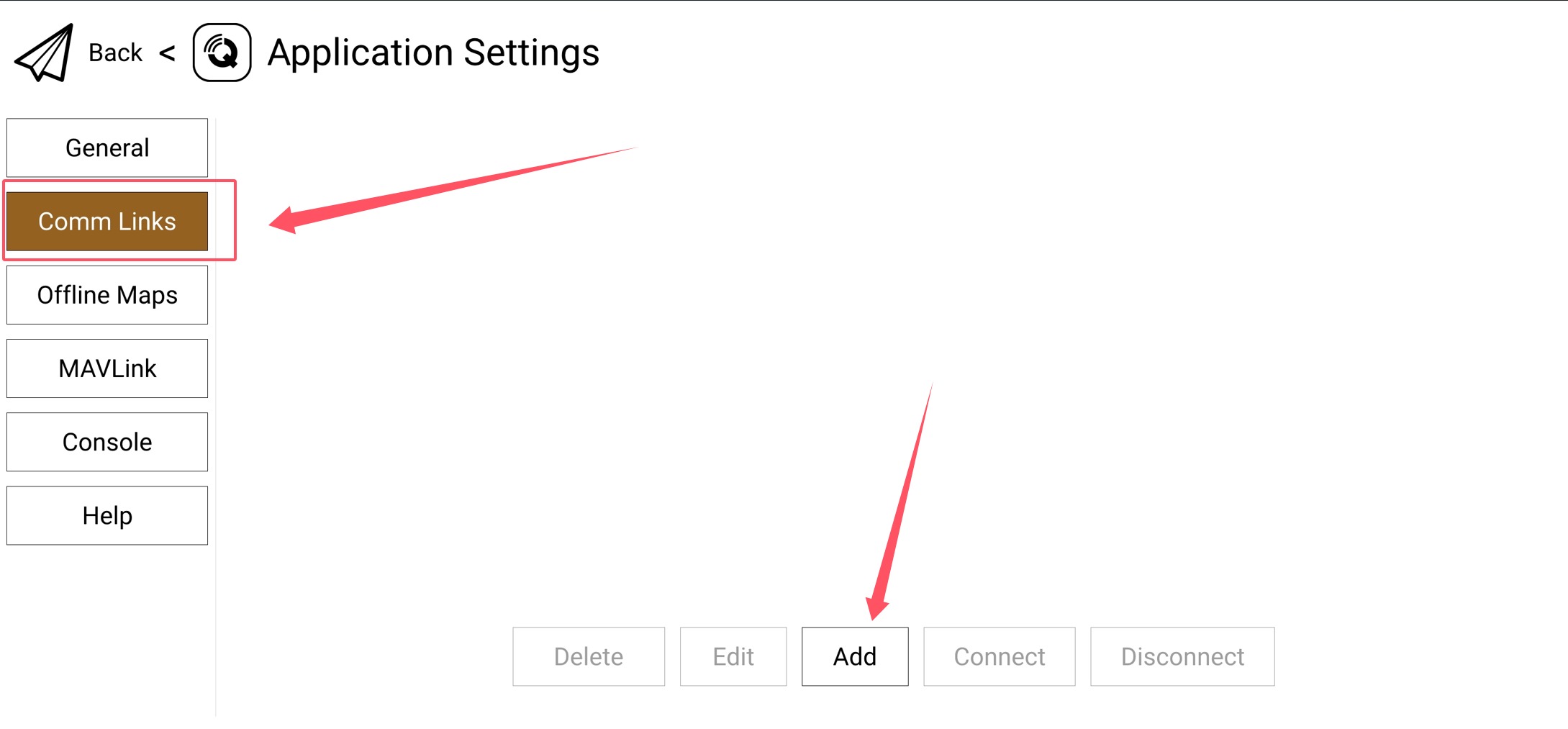
Add a Connection in QGroundControl
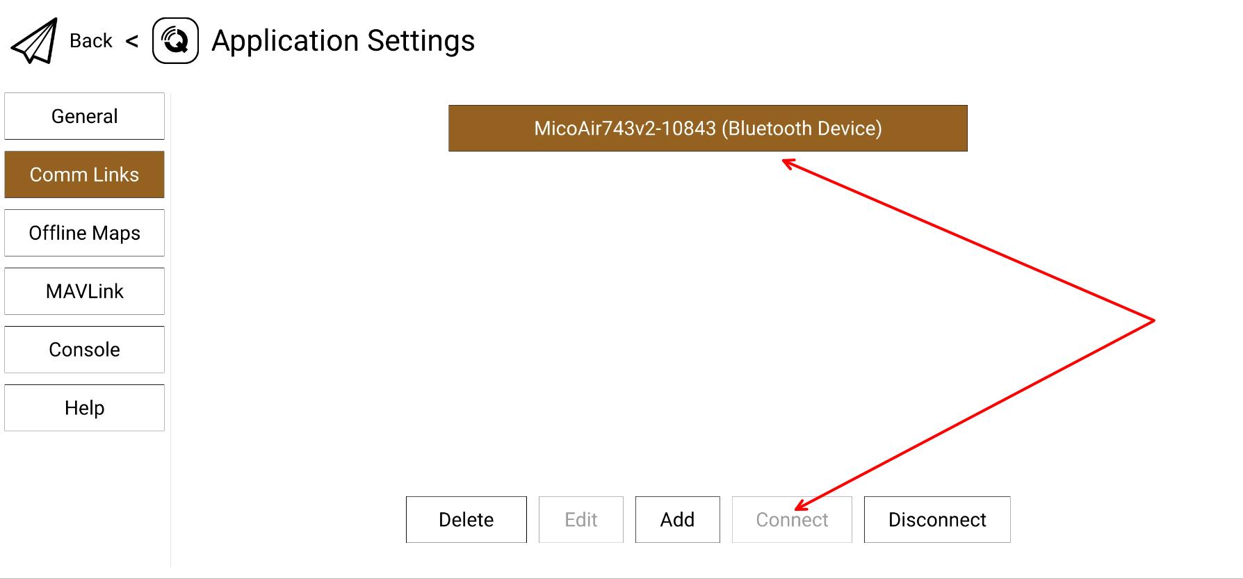
Go to Application Settings → Comm Links and click Add.
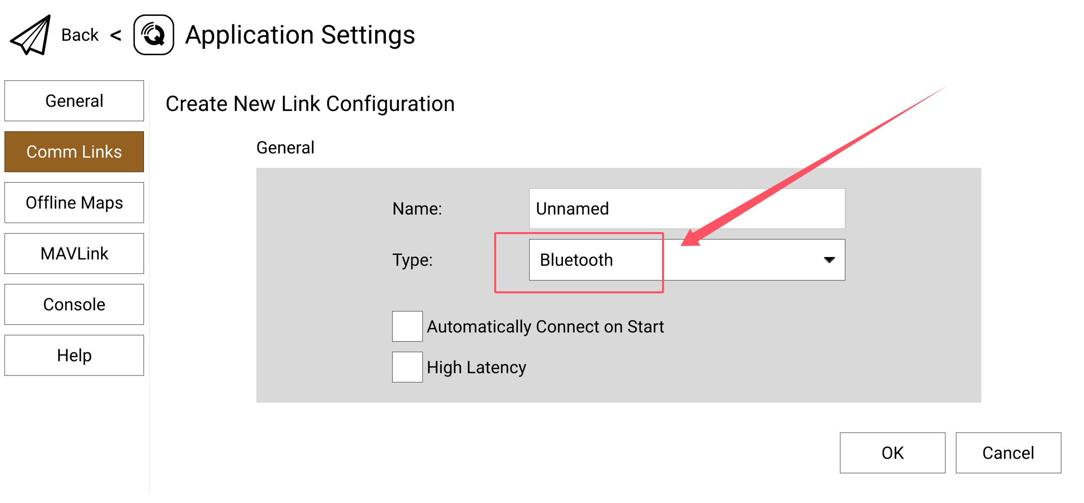
Set the connection type to Bluetooth.
Click Scan and select the flight controller Bluetooth device whose name begins with MicoAir.
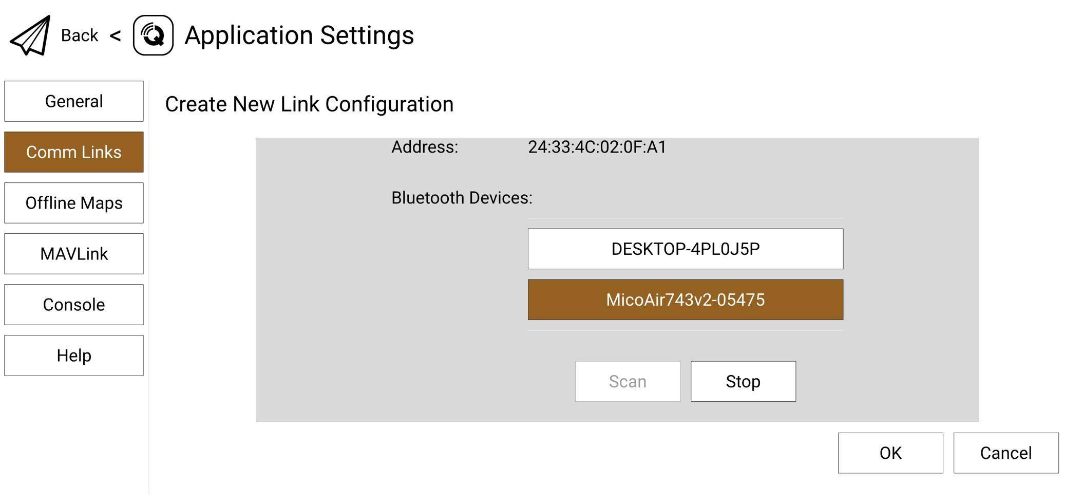
Older official tutorials may show a device name such as
MicoAir743v2-xxxxx. Use the name detected by the phone and printed on the device label.
Select the device and click Connect. The green Bluetooth status indicator remains on after a successful connection.
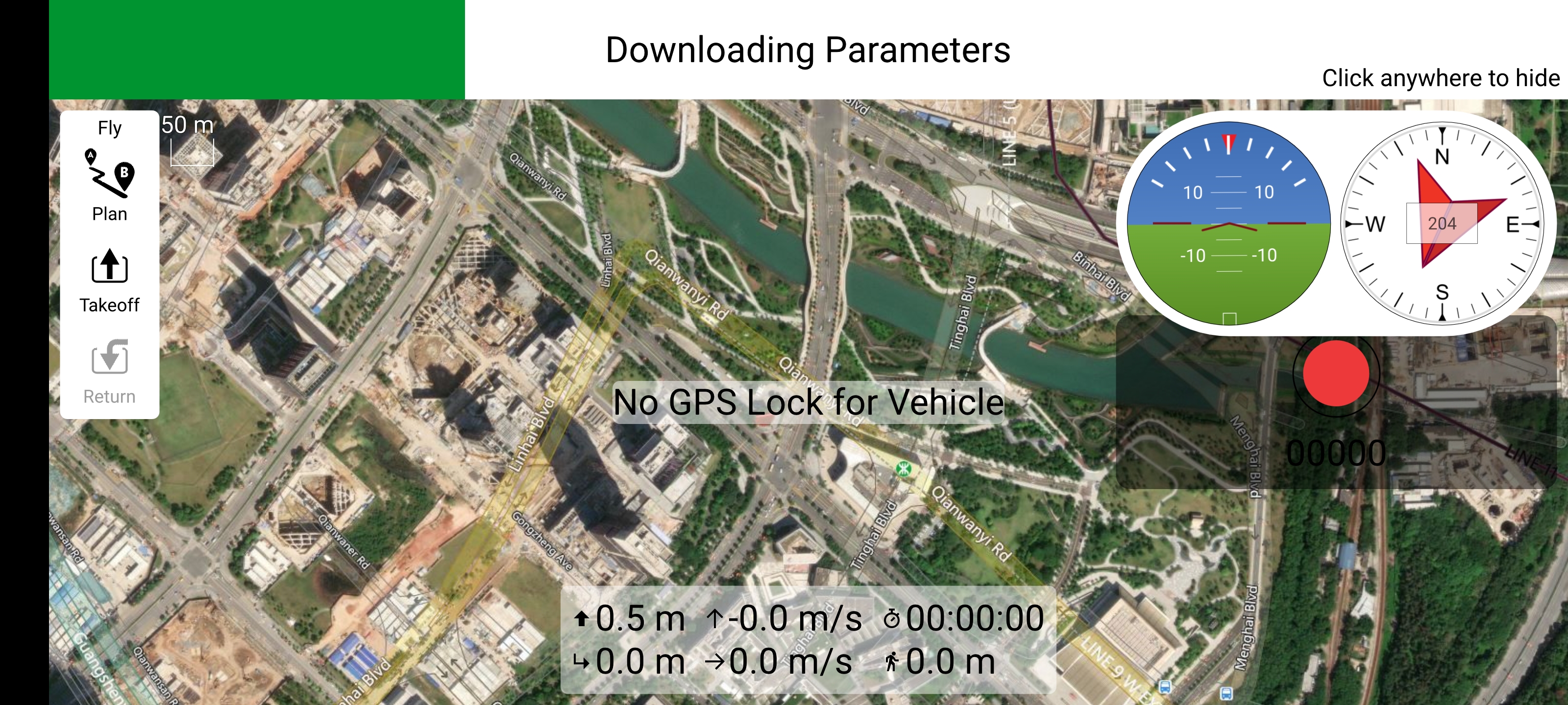
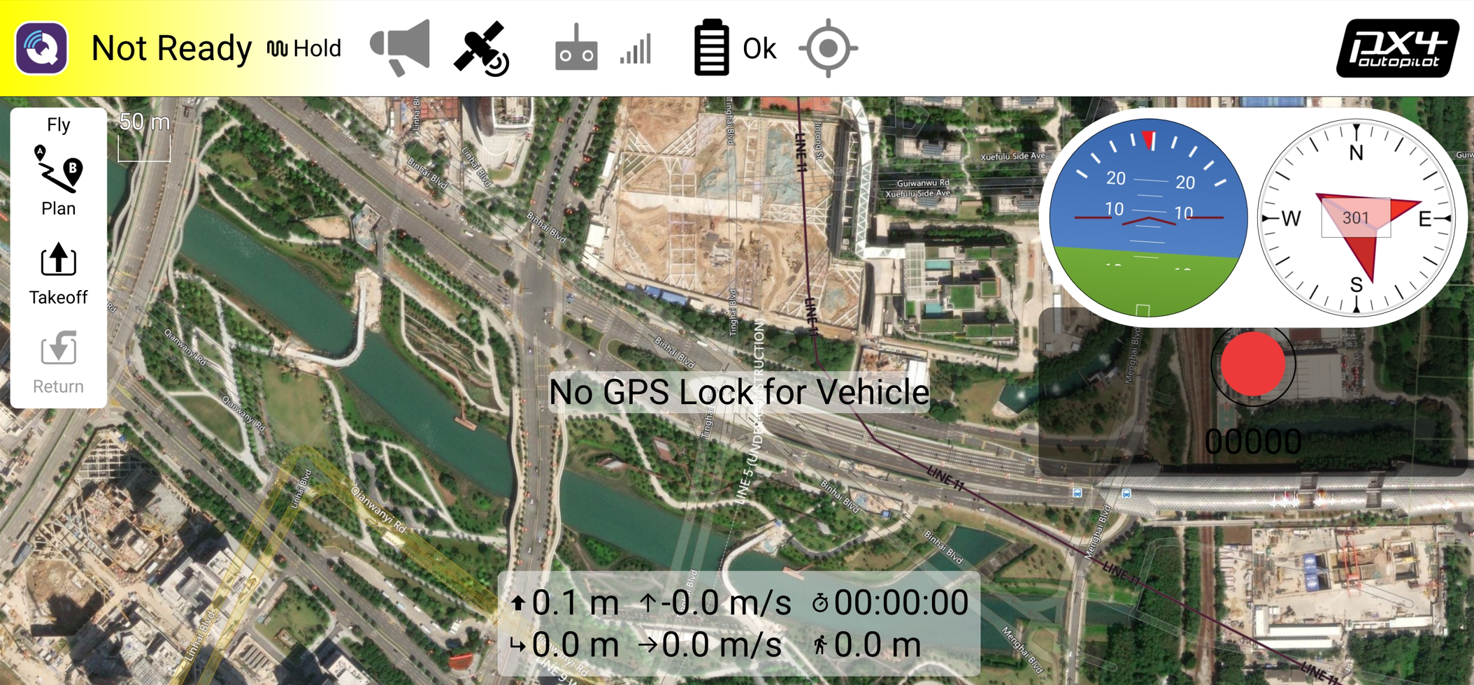
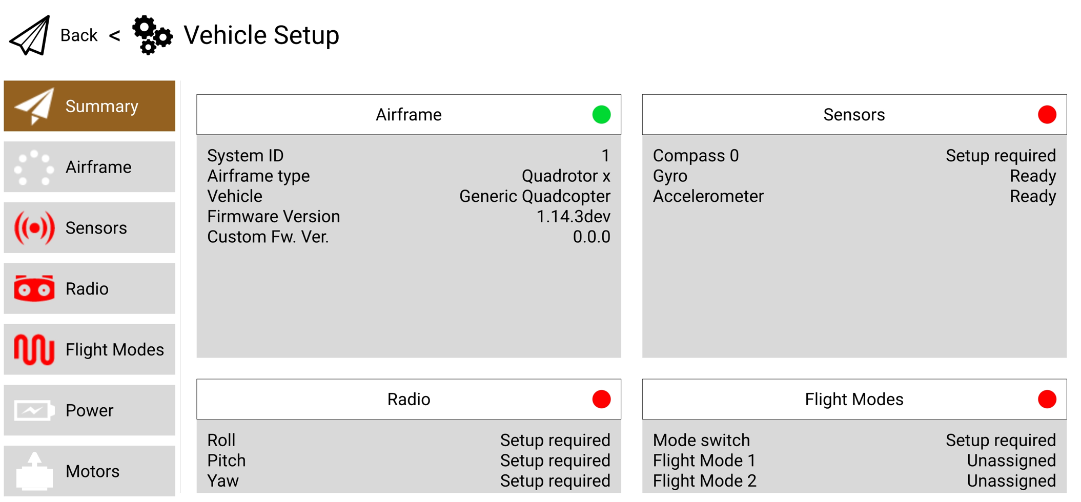
QGroundControl loads the parameter list:
Flight Controller Firmware
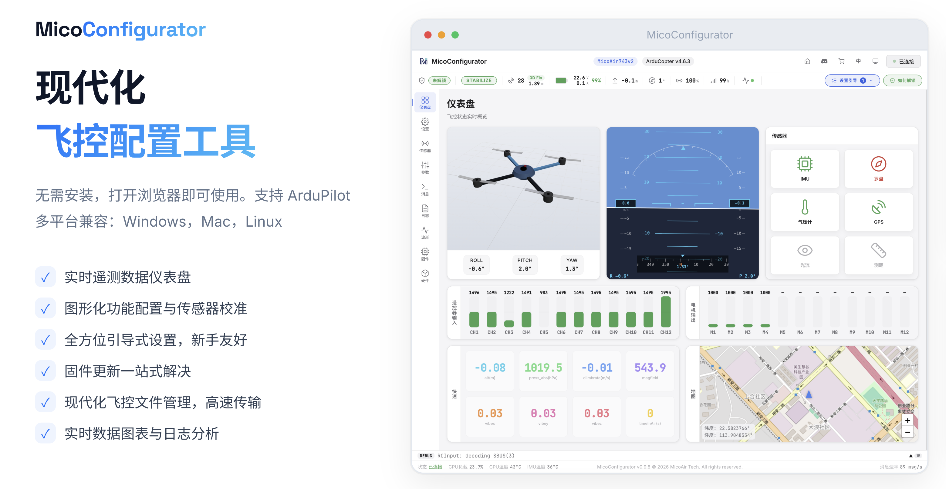
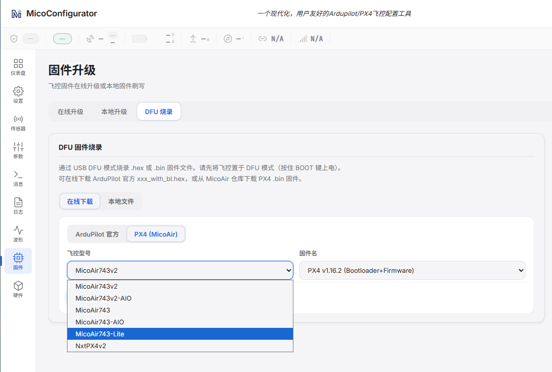
MicoConfigurator is a browser-based flight controller configuration tool. It can configure flight controllers running ArduPilot or PX4 and update firmware online, from a local file, or in DFU mode.
ArduPilot
-
Firmware target:
MicoAir743-Lite -
Firmware can be updated through MicoConfigurator or Mission Planner
PX4
-
Firmware target:
micoair_h743-lite -
Firmware can be flashed with MicoConfigurator, downloaded from PX4 Releases, or built from source
Official PX4 firmware build guide
Build the bootloader:
make micoair_h743-lite_bootloader
Build the default firmware:
make micoair_h743-lite_default
Betaflight
INAV
INAV does not currently support this board because support for its ICM45686 IMU has not yet been implemented.
Firmware Flashing and Recovery
Normal Upgrade
- Back up the current parameters.
- Select the correct target in MicoConfigurator, Mission Planner, or the applicable configurator.
- After flashing, power-cycle the board and recheck the sensors, serial ports, and output settings.
Enter DFU Mode
- Disconnect the battery and USB cable.
- Press and hold
BOOT. - While continuing to hold the button, connect USB Type-C.
- Release the button after the DFU device is detected.
- Flash the correct firmware from the DFU page in MicoConfigurator.
Troubleshooting
Bluetooth Device Not Found
- Wait at least 3 seconds after power-up, then press and hold
BOOTfor approximately 2 seconds - Confirm that the blue power indicator is on
- Grant Android Bluetooth and Nearby devices permissions
- Confirm that UART8 uses
115200baud and has not been reassigned - Remove the old connection record and scan again
USB Connection Fails
- Use another USB Type-C cable that supports data transfer
- Try another USB port and avoid an underpowered hub
- Check whether a serial or DFU device appears
Motors Do Not Respond During Testing
- Confirm that the propulsion battery is connected
- Check output channels, frame type, and ESC protocol
- For Bluejay/AM32 ESCs, try
DShot300first - Remove all propellers before testing
Board Does Not Boot After Flashing the Wrong Firmware
Hold BOOT while connecting USB to enter DFU mode, then select firmware for MicoAir743-Lite or micoair_h743-lite as appropriate.
Related Resources
- MicoConfigurator
- Flight Controller Firmware Flashing Guide
- ArduPilot Basic Setup Guide
- Connecting a MicoAir743v2/MicoAir743-Lite to a PC over Bluetooth
- Official ArduPilot documentation
- Official PX4 documentation
- QGroundControl Download and Install
- Betaflight Configurator
Appendix A: Pinout Table
| Function | Bus / Channel | Signal | MCU Pin |
|---|---|---|---|
| ICM45686 | SPI3 | MOSI / MISO / SCLK / CS / DR | PD6 / PB4 / PB3 / PD4 / PD5 |
| SPA06 | I²C2 | SCL / SDA / DR | PB10 / PB11 / PD0 |
| Motor outputs | TIM1 | M1 / M2 / M3 / M4 | PE14 / PE13 / PE11 / PE9 |
| Motor outputs | TIM3 | M5 / M6 / M7 / M8 | PB1 / PB0 / PA7 / PA6 |
| Motor outputs | TIM15 | M9 / M10 | PE5 / PE6 |
| Motor outputs | TIM4 | M11 / M12 | PD12 / PD13 |
| Motor outputs | TIM12 | M13 / M14 | PB14 / PB15 |
| LED / PWM15 | TIM4 CH3 | LED strip | PD14 |
| Buzzer | GPIO | Buzzer | PD15 |
| Status LEDs | GPIO | Red / Blue / Green | PE3 / PE4 / PE2 |
| I²C peripheral port | I²C1 | SDA / SCL | PB9 / PB8 |
| UART1 | USART1 | TX / RX | PA9 / PA10 |
| UART2 / VTX-HD | USART2 | TX / RX | PA2 / PA3 |
| UART3 / GPS | USART3 | TX / RX | PD8 / PD9 |
| UART4 | UART4 | TX / RX | PA0 / PA1 |
| UART5 | UART5 | TX / RX | PB6 / PB5 |
| UART6 / RCIN | USART6 | TX / RX | PC6 / PC7 |
| UART7 / ESC telemetry | UART7 | RX | PE7 |
| UART8 / Bluetooth | UART8 | TX / RX | PE1 / PE0 |
| USB | USB FS | DM / DP | PA11 / PA12 |
| microSD | SDMMC1 | D0 / D1 / D2 / D3 | PC8 / PC9 / PC10 / PC11 |
| microSD | SDMMC1 | CLK / CMD | PC12 / PD2 |
| Debug interface | SWD | SWDIO / SWCLK | PA13 / PA14 |
| Battery monitoring | ADC | Voltage / Current | PC0 / PC1 |