
Docs directory
Table of contents
MicoVIO Visual-Inertial Odometry User Manual
Product Overview
MicoVIO is a monocular visual-inertial odometry module designed and manufactured by MicoAir Tech. It combines a camera, an IMU, and ToF ranging to output relative position, velocity, and attitude in real time in GPS-denied environments or areas with limited satellite reception, providing reliable state information for drone hovering, position hold, and autonomous navigation.
The module uses a high-dynamic-range global-shutter image sensor, a wide-angle lens with a large aperture, and extensively optimized vision algorithms. It offers strong environmental adaptability and excellent low-light performance, handling challenging conditions such as abrupt indoor/outdoor lighting changes, low-texture surfaces, and reflective floors. Reliable tracking is maintained even during yaw spins and banked orbit maneuvers.
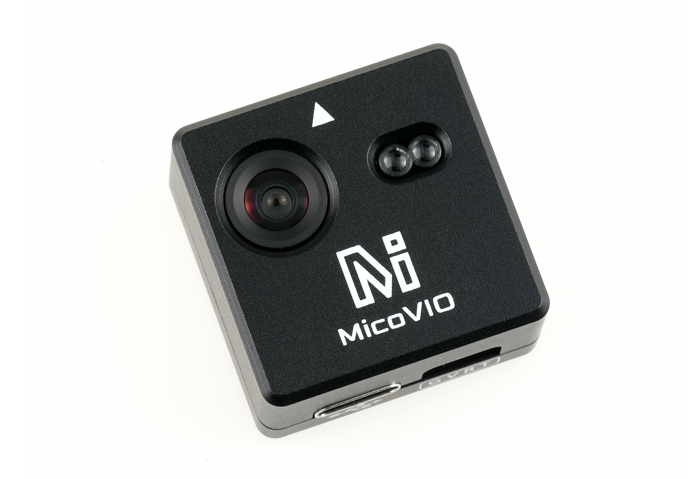
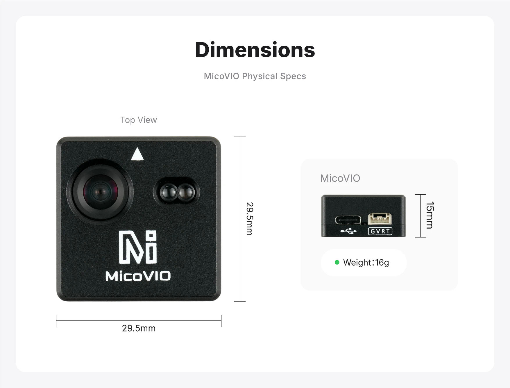
Measuring just 29.5 × 29.5 × 15 mm and weighing approximately 16 g, MicoVIO combines a compact form factor with powerful performance, making it easy to integrate into frames of different sizes. It outputs MAVLink data over a serial interface and is ready to use when connected to a flight controller. It supports open-source autopilot firmware including ArduPilot and PX4, enabling precise hovering and stable flight without GPS, with a control experience comparable to consumer aerial-photography drones.
Purchase
Specifications
Positioning and Tracking
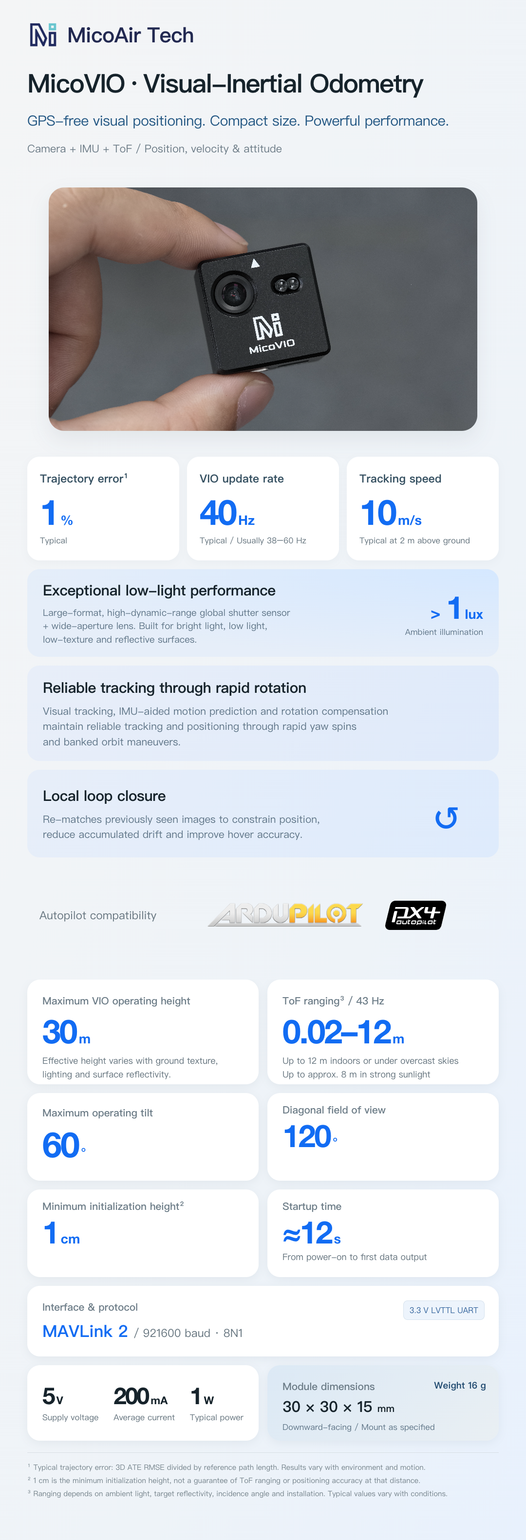
- Positioning method: Visual-inertial fusion using the camera and IMU, with an integrated ToF range sensor providing height information
- Output data: Relative position, three-axis velocity, attitude, distance to the ground, and positioning quality information
- VIO trajectory positioning error: 1% (typical)¹
- VIO update rate: Typically 40 Hz; generally 38–60 Hz, depending on scene texture complexity
- VIO tracking speed: A typical tracking speed of up to 10 m/s at a height of 2 m above the ground; varies with operating height, lighting, texture, and motion
- Maximum VIO operating height: 30 m; the effective height varies with scene texture, lighting, and ground reflectance
- Minimum ground clearance for initialization: 1 cm²
- Maximum operating tilt angle: 60°
- Maximum tracking angular rate: 300°/s
- Local loop closure: Enabled by default; improves hover and position-hold accuracy by re-matching images, without affecting dynamic flight performance
- Startup time: Approximately 12 seconds from power-on until data output begins
Vision and Ranging
- Lens FOV: 120° diagonal field of view
- Ambient illumination requirement: >1 lux, with strong low-light performance
- ToF ranging distance: 0.02–12 m; up to 12 m indoors or outdoors under overcast skies, and approximately 8 m outdoors in bright sunlight³
- ToF update rate: 43 Hz
Communication Interface and Protocol
- Output protocol: MAVLink 2
- Odometry message: ODOMETRY (message ID: 331)
- Ranging message: DISTANCE_SENSOR (message ID: 132)
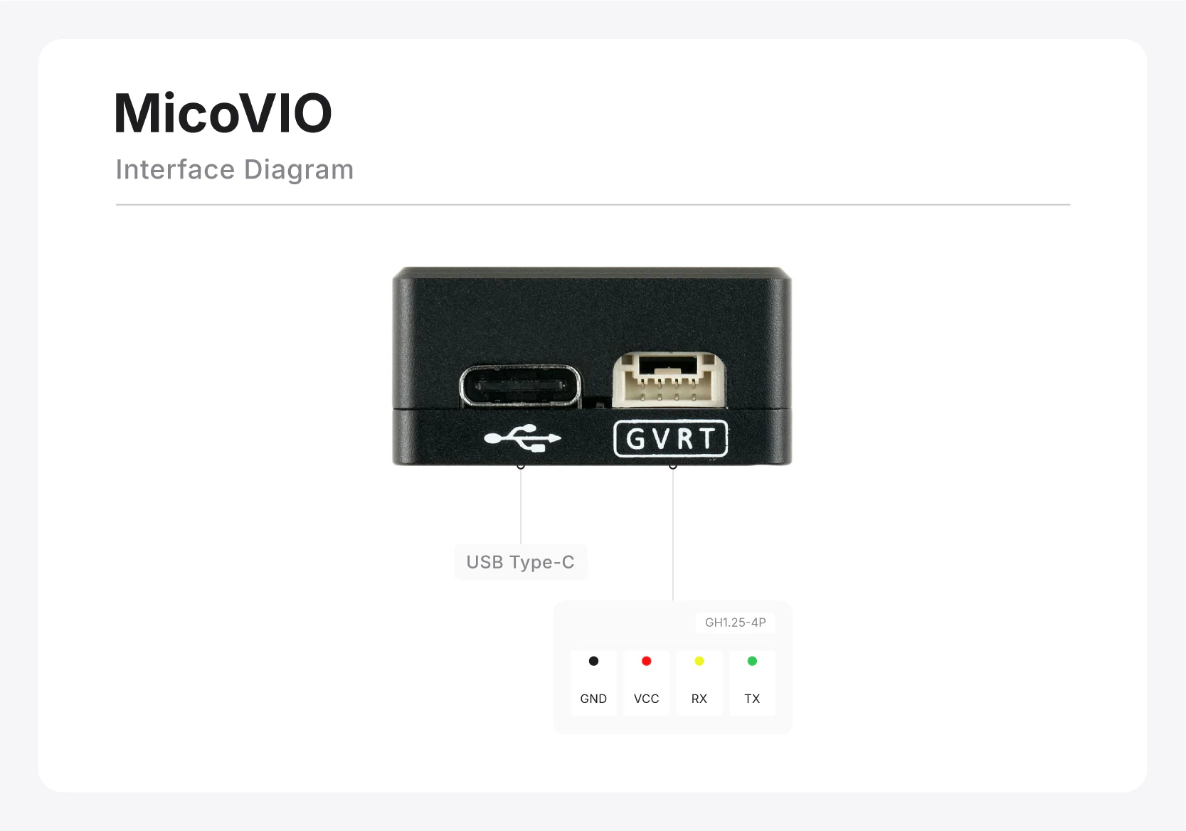
- Communication interface: 3.3 V LVTTL serial
- Baud rate: 921600; 8 data bits, no parity, 1 stop bit (8N1)
- Connector: GH1.25-4P
Electrical and Mechanical Specifications
- Supply voltage: 5 V
- Average operating current: Approximately 200 mA
- Typical operating power: Approximately 1 W
- Module dimensions: 29.5 × 29.5 × 15 mm
- Module weight: 16 g
- Mounting: Downward-facing, secured in the specified orientation
Specification notes
¹ The typical 1% trajectory positioning error is calculated as the three-dimensional ATE RMSE divided by the total reference trajectory length. Actual performance varies with environmental and motion conditions.
² This is the minimum ground clearance at which initialization is permitted. It does not guarantee ToF ranging or positioning accuracy at that distance.
³ Actual ranging performance depends on ambient light, target reflectivity, angle of incidence, and mounting conditions.
Features
Low Cost and High Performance
Visual-inertial odometry (VIO) is a key technology for stable GPS-denied flight and is widely used in high-end consumer drones. However, cost, size, weight, and integration complexity remain barriers to visual positioning for the open-source flight-controller community, DIY enthusiasts, and industrial applications. Traditional open-source VIO solutions often rely on high-performance onboard computers and complex sensor configurations, making it difficult to achieve both compact size and low cost.
Drawing on years of sensor research and development, MicoAir Tech has continuously optimized its vision algorithms and jointly designed the hardware and software to integrate complete visual positioning capabilities into a module measuring just 29.5 × 29.5 × 15 mm and weighing approximately 16 g. With its affordable price, compact size, and excellent performance, MicoVIO makes GPS-denied hovering, position hold, and autonomous navigation accessible to more drones.
Excellent Low-Light Performance and Environmental Adaptability
MicoVIO uses a premium large-format, high-dynamic-range global-shutter image sensor with excellent low-light capabilities, maintaining effective tracking even in dimly lit environments. It is extensively optimized for challenging conditions such as abrupt lighting changes, bright light, low-texture surfaces, and reflective floors, enabling stable operation in the vast majority of real-world scenarios. With supplemental lighting, it can also operate in otherwise completely dark environments such as tunnels and mines.
Robust Tracking and Resistance to Estimation Divergence
Most open-source VIO projects are highly prone to estimation divergence in practical use, making them difficult to use in production environments. MicoVIO, by contrast, maintains stable operation without divergence under conditions such as large lighting changes, severe impacts, and rapid attitude changes. It also maintains reliable visual tracking and positioning during drone yaw spins and banked orbit maneuvers.
Local Loop Closure
Loop closure is an important capability in visual SLAM systems, but it places high demands on computing resources and is generally unavailable in VIO systems. Through streamlined, efficient algorithm design, MicoVIO implements local loop closure on a compact, low-cost platform with limited processing resources. By re-matching previously captured images, it provides visual position constraints that suppress accumulated drift and further improve hover and position-hold accuracy.
Accurate Trajectory Estimation
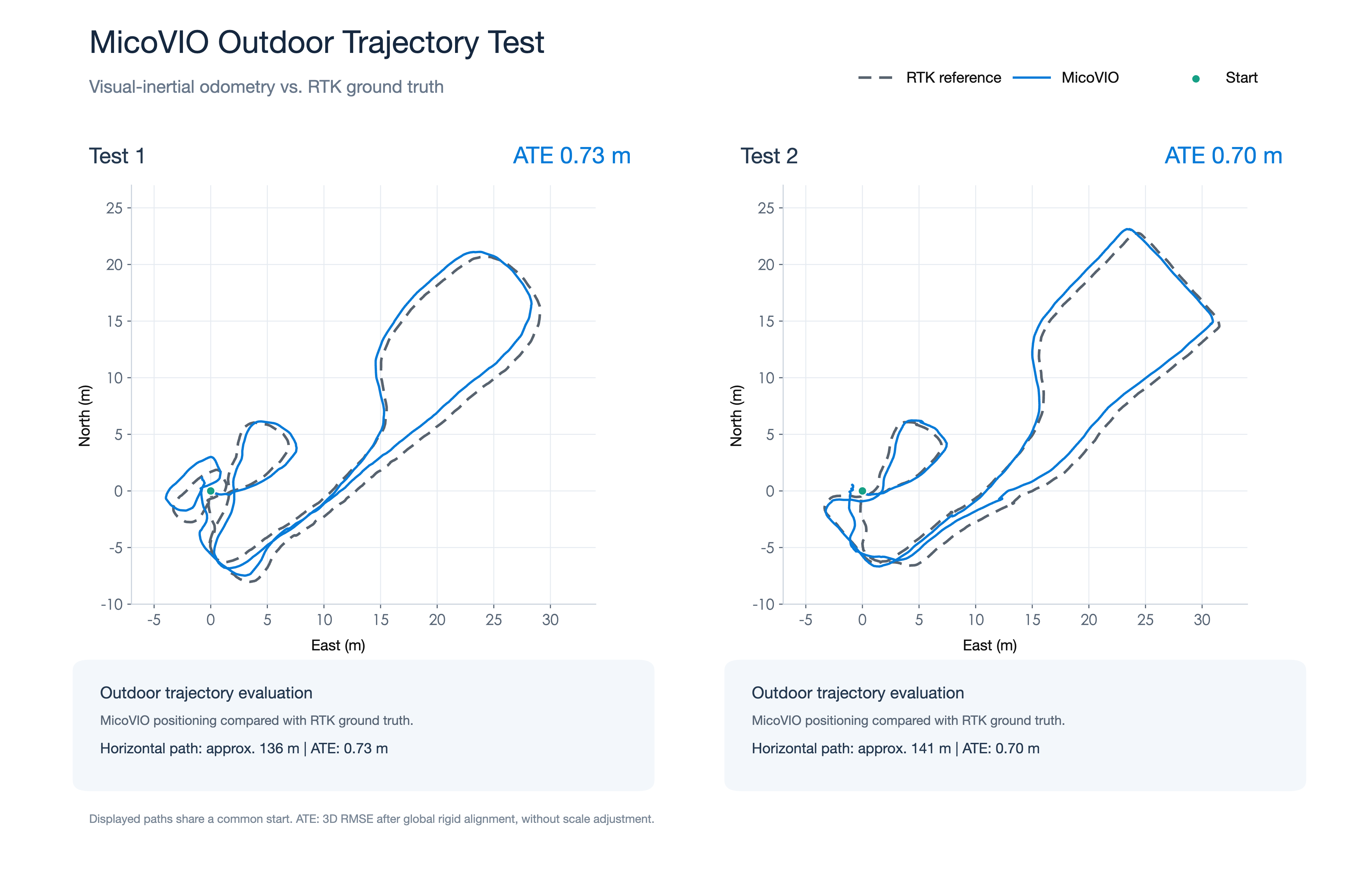
MicoVIO outputs relative position, three-axis velocity, and attitude in real time, meeting the requirements for stable hovering while also providing accurate position references for trajectory tracking and autonomous navigation. With a typical trajectory positioning error of 1%, it offers excellent trajectory reconstruction despite its small size and low cost. This accurate trajectory estimation can enable GPS-denied return-to-home functionality when supported by the flight-control firmware.
Testing and Parameter Configuration
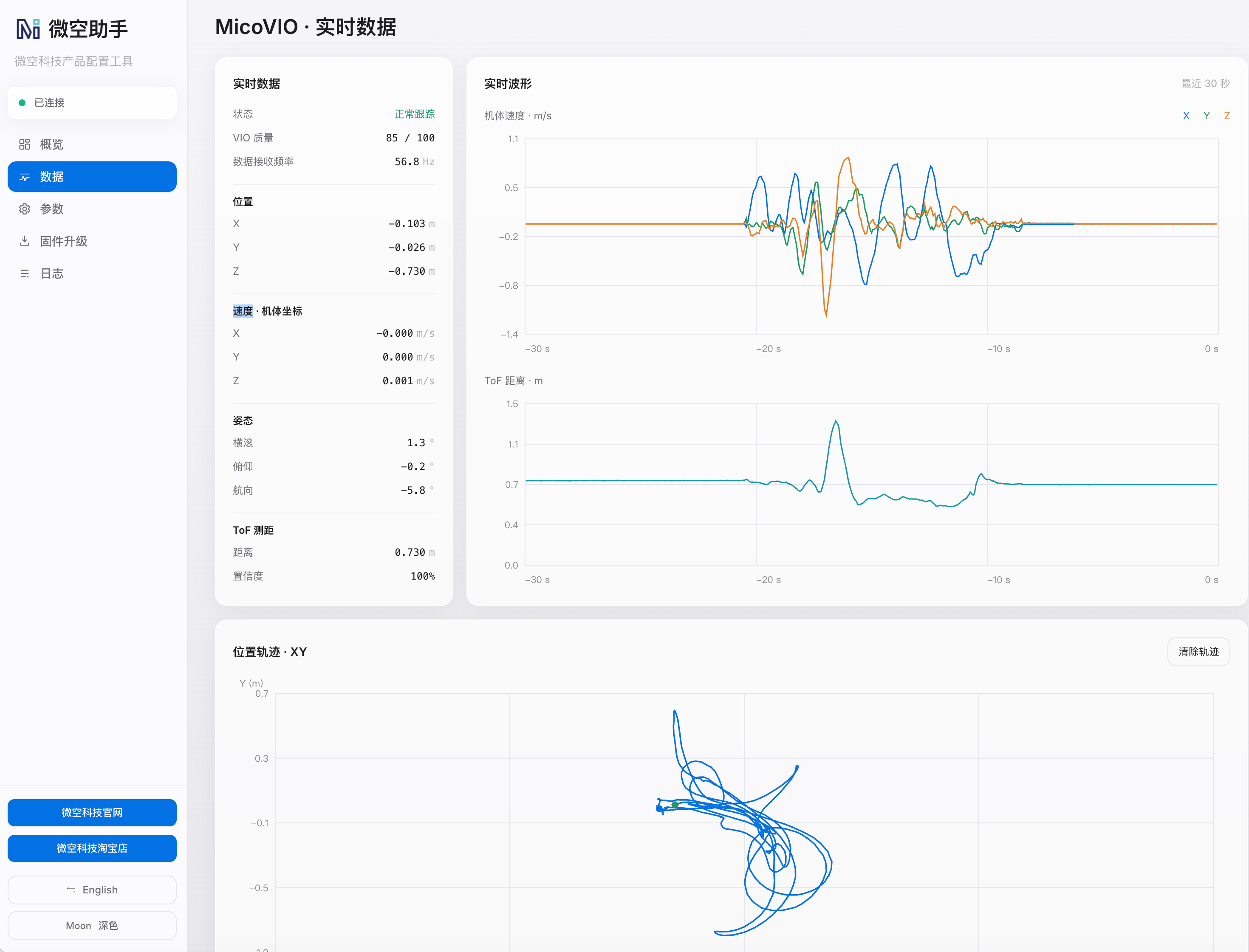
Connect MicoVIO to a computer using the module's USB port, then use MicoAssistant for testing and parameter configuration.
MicoAssistant: https://micoair.com/assistant/
Driver installation is generally unnecessary. Select the correct port when connecting; any baud rate can be used.
Interface Pinout
Flight Controller Wiring Diagram
Installation
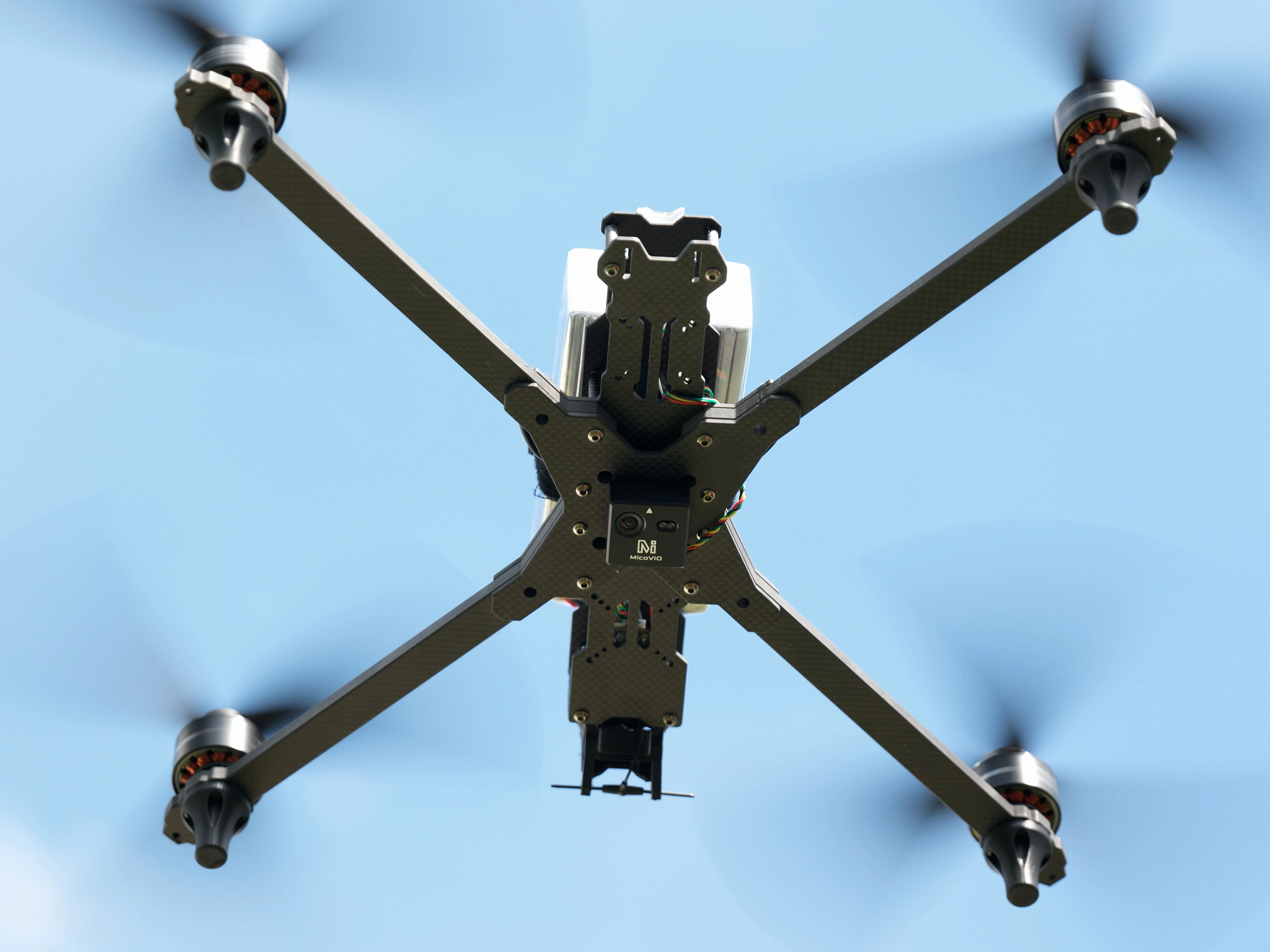
MicoVIO supports downward-facing installation only and is typically mounted on the underside of the airframe. The arrow on the module should point toward the nose. The mounting orientation (Yaw) can be adjusted in MicoAssistant in clockwise 45° increments when viewed from below.
Open-Source Flight Controller Configuration
We recommend MicoConfigurator for graphical flight-controller configuration.
ArduPilot
ArduPilot firmware version >= 4.5.2 is required.
Flight controllers based on an F405 MCU (with less than 2 MB of flash) generally do not support external vision by default.
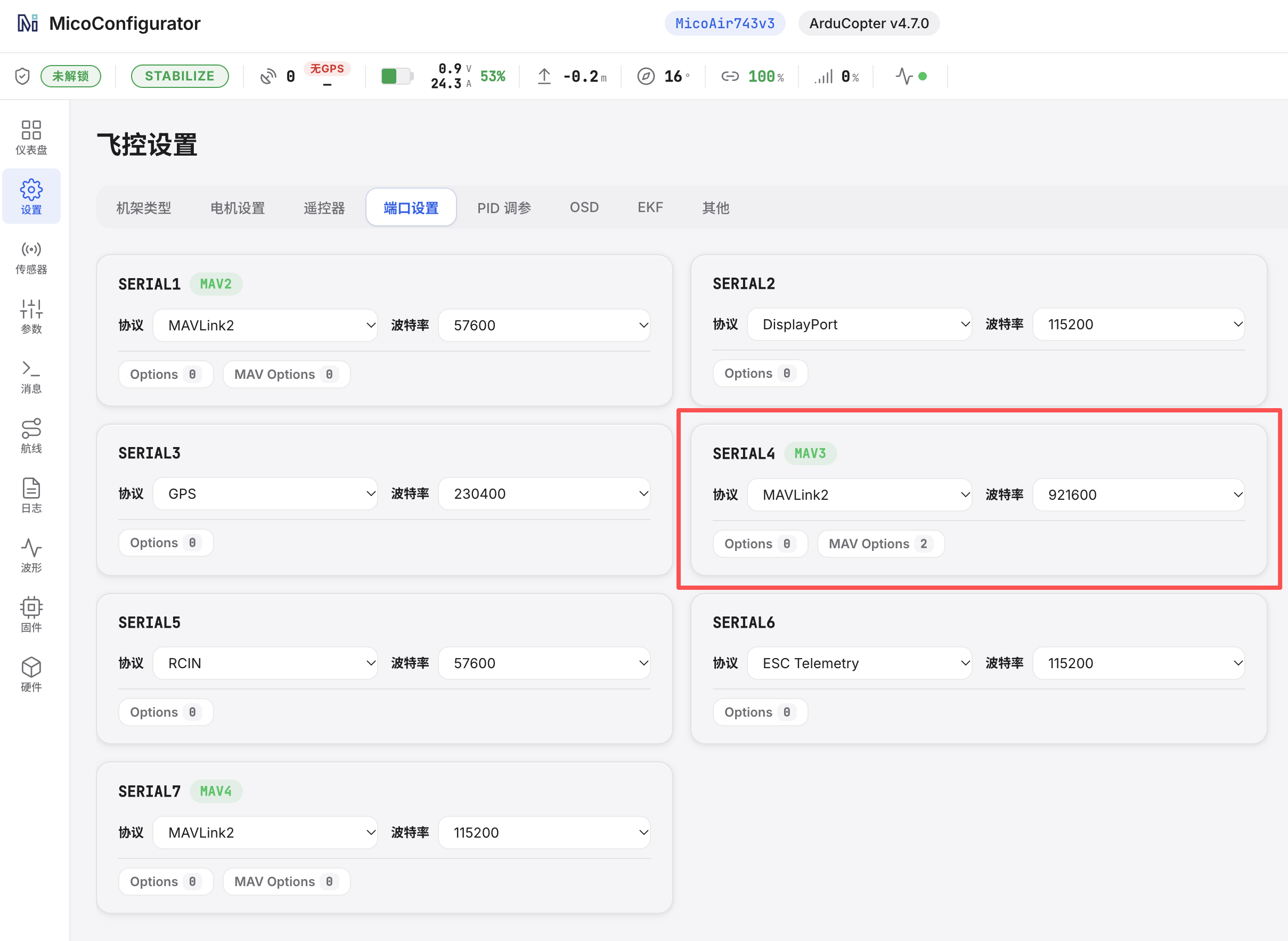
Port Configuration
SERIALn_BAUD  = 921
SERIALn_OPTIONS   1024 (before version 4.7)
MAVn_OPTIONS = 2 (after version 4.7)
SERIALn_PROTOCOL = 2
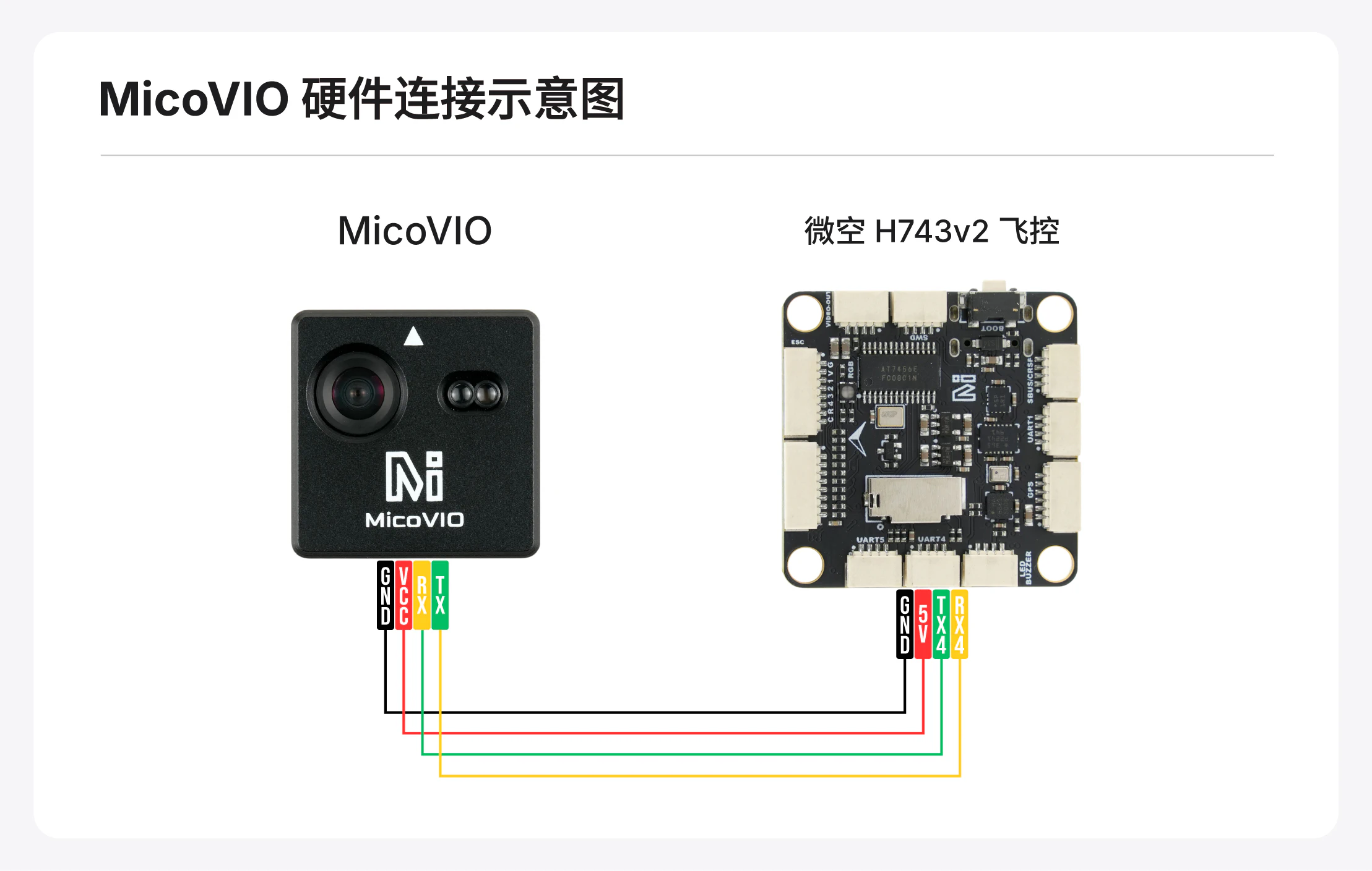
n depends on the flight-controller port to which MicoVIO is connected. Refer to the flight controller's manual for the mapping between physical ports and serial port numbers, or check the Port Settings page in MicoConfigurator.
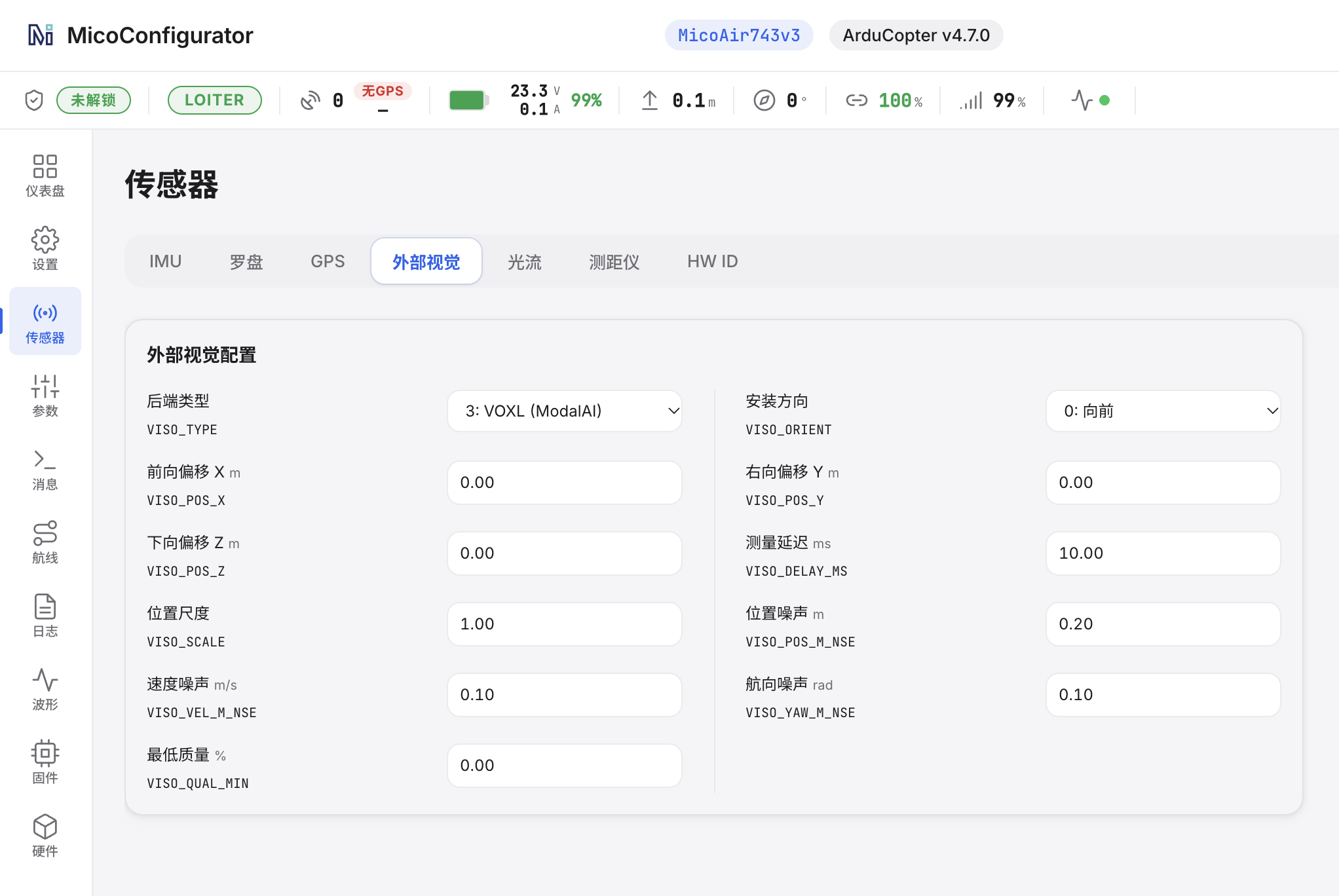
Visual Sensor Configuration
VISO_TYPE = 3
VISO_YAW_M_NSE = 0.1
Leave all other settings at their defaults. Restart the flight controller to apply the changes.
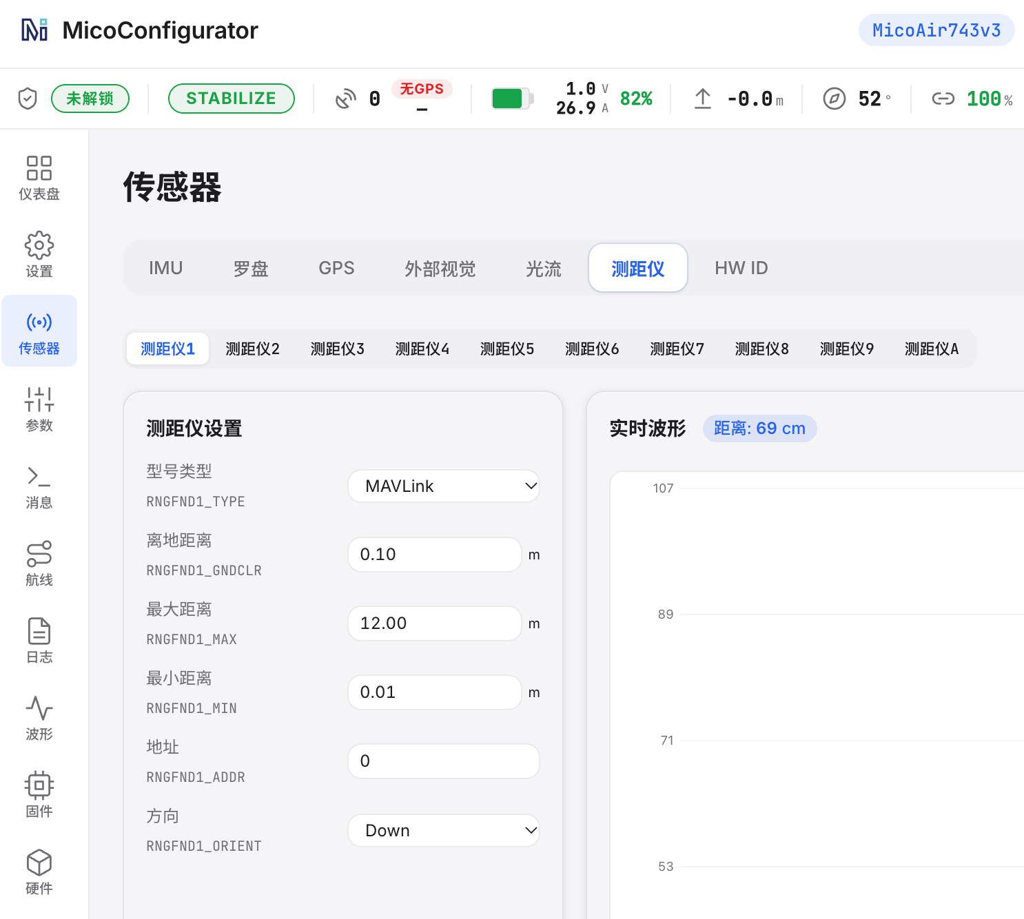
Rangefinder Configuration
RNGFND1_TYPE = 10
(n depends on the physical port used.)
Restart the flight controller or refresh the parameters. Note that the unit changes to m after version 4.7.0.
RNGFND1_MAX_CM = 1200
RNGFND1_MIN_CM = 1
RNGFND1_ORIENT = 25
EKF Configuration
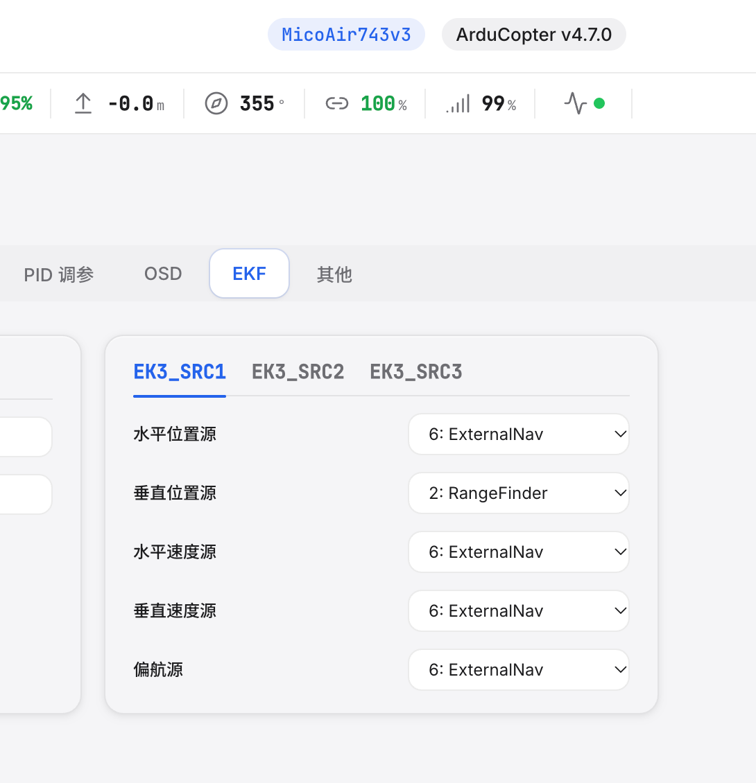
EK3_SRC1_POSXY = 6: ExternalNav
EK3_SRC1_POSZ = 2: RangeFinder
EK3_SRC1_VELXY = 6: ExternalNav
EK3_SRC1_VELZ = 6: ExternalNav
EK3_SRC1_YAW = 6: ExternalNav

EK3_SRC1_YAW can alternatively be set to 1: Compass, but ensure that VISO_TYPE = 3.
PX4
Port Configuration
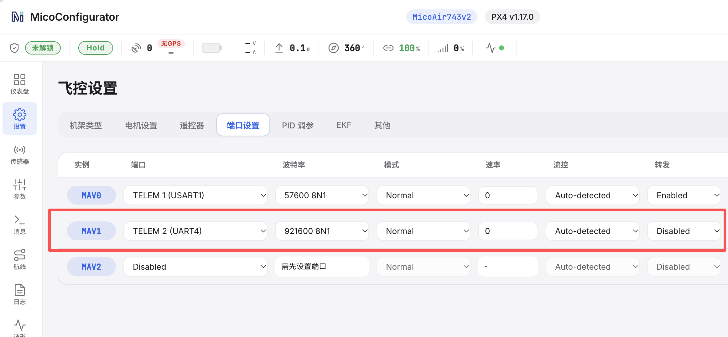
MAV_1_CONFIG   TELEM n
Restart the flight controller.
MAV_1_MODE = Onboard
MAV_1_FORWARD = Disabled
SER_TELn_BAUD   921600 8N1
n depends on the flight-controller port to which MicoVIO is connected. Refer to the flight controller's manual for the mapping between physical ports and serial port numbers, or check the Port Settings page in MicoConfigurator.
EKF Configuration
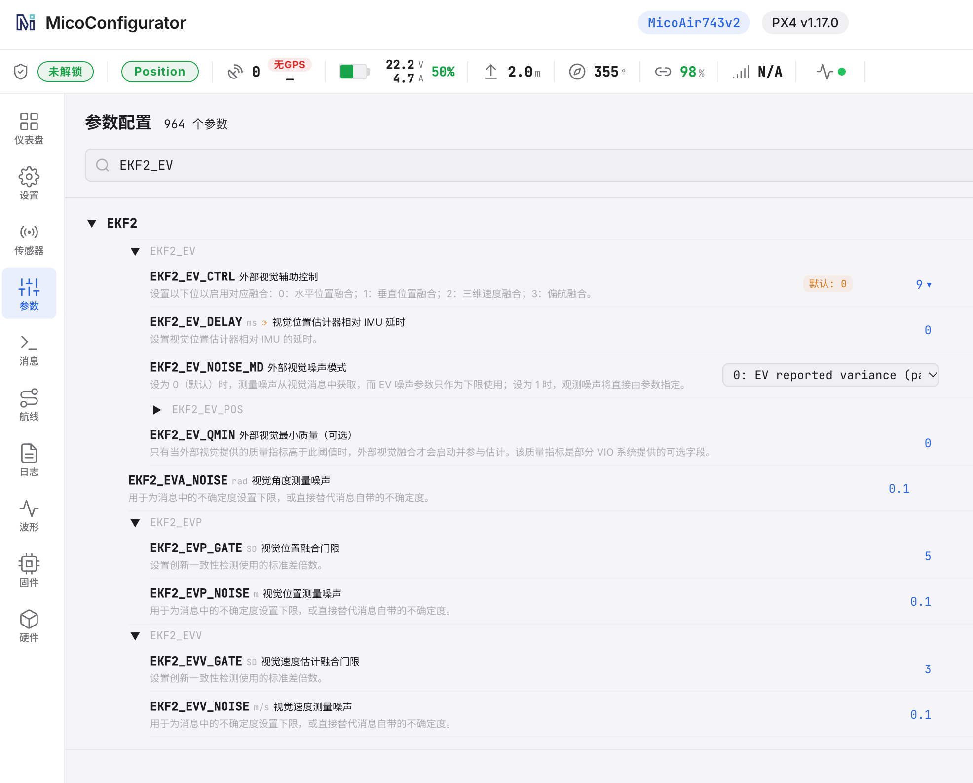
EKF2_EV_CTRL = 9
EKF2_HGT_REF = 2: Range sensor